Announcement

Collapse
No announcement yet.

Mike's Cabrio Build

Collapse
X
 
  • Filter
  • Time
  • Show
Clear All
new posts

  • Re: Mike's Cabrio Build

    Previously mentioned slip rings?

    If the alternator hasn't been used and dust, surface contamination and stuff has built up, then it may need the engine running to spin the crud away perhaps. It's low voltage and low, direct current so it won't punch it's way through like mains electric.

    Comment


    • Re: Mike's Cabrio Build

      Where are you measuring the continuity from? Have you tried directly on the alternator to chassis? Otherwise it could be a problem with the wire between the lamp and alternator.

      Comment


      • Re: Mike's Cabrio Build

        Originally posted by chris.cussen View Post
        Where are you measuring the continuity from? Have you tried directly on the alternator to chassis? Otherwise it could be a problem with the wire between the lamp and alternator.

        I tried from the warning lamp to alternator - no continuity. Added a wire from alternator to chassis - - then there was continuity. Therefore conclude I am not getting an earth through the alternator windings.


        However................my replacement ignition light arrived today so I've fitted it, and guess what? - It works!

        I just do not understand electricity!!!!!!!!!!!!!

        Move on.......

        Comment


        • Re: Mike's Cabrio Build

          Main loom wiring.

          Where have Cabrio owners routed the main wiring loom across the dash?

          I have tried behind the windscreen wiper mechanism, and then found several of the spurs to the dash foul on the wiper connector arms.
          So then I tried in front and above the wiper mechanism, attached via the dash top self tappers, but then found the main loom fouled the wiper mechanism when it returned under the dash.

          The only solution appears to be over the top of the wiper mechanism all the way across , including the wiper motor itself, and then return under the dash - problem is my wires are not long enough to do this?

          Mmm........some lateral thinking is required.

          Any advice?
          Last edited by Mike; 11-07-13, 12:57 PM.

          Comment


          • Re: Mike's Cabrio Build

            Not sure which loom you are using, I bought mine from Premier wiring.
            I've routed all the connections to the steering colum switch gear and guages along the bottom of the dash. Relays are mounted inside above the passenger footwell The fuze box is on top of the bulkhead. The front wiring loom exits near the top of the passenger footwell. One spur runs forward to the lights etc, and another across to the ECU. heater blower and sensors on the engine.
            The rear spur comes of the main loom just before the hole in the bulkhead. I have run it along the passanger cill and into the boot.
            Chris
            Last edited by chris_cussen; 11-07-13, 12:56 PM. Reason: typos

            Comment


            • Re: Mike's Cabrio Build

              Chris

              Do you have a photo of your wiring at the build stage?

              Mike

              Comment


              • Re: Mike's Cabrio Build

                Sorry, but no. I didn't photograph very much of the build.

                Comment


                • Re: Mike's Cabrio Build

                  Medal? Medal? Medal?
                  ( for those who remember Muttley (and Dick Dastardly) in The Whacky Races cartoon

                  I can almost say my electrics are finished now! - Almost because I have not been able to test my speedo, or rev counter working correctly yet, though I have been able to set the pulse counter on the speedo. So as long as the Hall effect sender senses the three nuts on the prop shaft there is no reason why it shouldn't (but experience now tells me that is no guarantee of success!)

                  Its difficult to show anything which reflects the amount of time the electrics has taken me, but at least I have a photo of all the lights on! (the Fog light only comes on with Main Beam/Dip, not with side lights, as required by IVA)


                  All Rear Lights On.jpg

                  .....and I have courtesy lights which work nicely as the doors open, and electric windows that go up and down! Yeah!

                  I decided not to go for the electric central locking - it seems a bit superfluous in a car that you can reach both door locks from the drivers seat, and, I may well remove the Sierra key barrel, and handle, post IVA, to replace them with the original older Mini door handles which will look more in keeping with the age of the Cabrio's style.

                  Next?
                  Change the diff - from 3.38 to 3.14.
                  Last edited by Mike; 23-07-13, 08:36 PM.

                  Comment


                  • Re: Mike's Cabrio Build

                    Mike,

                    My attempt at using a hall effect sensor failed miserably and I have ended up using the output from the speed sensor in my diff. That output is solid and reliable with a stable reading throughout the speed range.

                    The problem that I found with the hall effect sensor interacting with the propshaft bolts is that the spacing between the bolts and the sensor is absolutely critical. There is virtually no useable tolerance. The instructions said 2mm max but when I spoke to Caerbont Instruments they said it needed a constant 1mm. I found that as soon as any load is put on the drive chain, (and assuming the sensor is not secured to the drive chain) the spacing varies and the speedo readings become erratic and unstable. I tried to find somewhere to mount the sensor on the drive chain but that proved impossible, so that's why I went back to the diff out put. I'm not sure whether you have one in your set up though.......................

                    Comment


                    • Re: Mike's Cabrio Build

                      Originally posted by nigel View Post
                      Mike,

                      My attempt at using a hall effect sensor failed miserably and I have ended up using the output from the speed sensor in my diff. That output is solid and reliable with a stable reading throughout the speed range.

                      The problem that I found with the hall effect sensor interacting with the propshaft bolts is that the spacing between the bolts and the sensor is absolutely critical. There is virtually no useable tolerance. The instructions said 2mm max but when I spoke to Caerbont Instruments they said it needed a constant 1mm. I found that as soon as any load is put on the drive chain, (and assuming the sensor is not secured to the drive chain) the spacing varies and the speedo readings become erratic and unstable. I tried to find somewhere to mount the sensor on the drive chain but that proved impossible, so that's why I went back to the diff out put. I'm not sure whether you have one in your set up though.......................

                      Hi Nigel

                      Sadly I will not have the option of a diff sensor, as the Sierra diff does not have one.

                      However, my sensor mount is attached to the gearbox, and set to read the nuts on the gearbox output flange, so there should not be any relative movement even under load.
                      I copied Simon Gregory's arrangement (and sensor from RS Components) which still works in his Cabrio, so I can still cling to the hope it will work.


                      It's useful to know the clearance is critical though if I have any problems................ I will be able to find out once I have changed my diff, and re-installed the tank and all its connections, (hopefully for the final time before IVA!)
                      Last edited by Mike; 24-07-13, 09:43 PM.

                      Comment


                      • Re: Mike's Cabrio Build

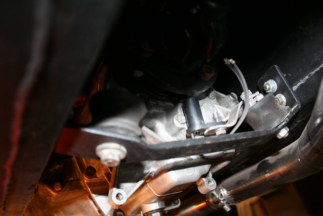
                        200BHP into the Sierra diff has always caused me to pause for thought - not for the diff itself, which I believe will take much more, but for the original Ford rear D mount diff support, and the significant degree of rotation it is designed to allow.
                        Those following my build will remember I decided (felt I had to!) make a stronger less flexible support to control the degree of diff rotation in my narrowed down transmission tunnel, or face fuel lines and brake pipes being damaged by an errant prop shaft.


                        Intially, I copied the design of Ford's later Scorpio, which has two non voided rubber bushes, welding them to the ends of a T-bar which picked up on the same fixings as the D mount.

                        IMG_2738.jpg

                        Once made, I was aware that the design was inherantly weak with two bolt fixings close together in a straight line perpendicular to the axis of rotation. Triangulating the fixings would make the design so much stronger.

                        Encouraged by Peter Licence (GreyV8Peter), I have used 4 pieces of 6mm aluminium plate to triangulate the ends of the T bar down to two other diff case fixing points.

                        This is the result:

                        IMG_4488.jpg

                        IMG_4485.jpg

                        The design is much stronger now, and I am confident this will control the movement of the diff under hard acceleration.
                        Of course I can still fret about whether the two bushes will have sufficient vibration damping left in them to provide me with a quiet ride for my Grand Tourer Cabrio? ..................only time will tell.
                        Last edited by Mike; 09-08-13, 06:34 PM.

                        Comment


                        • Re: Mike's Cabrio Build


                          Holiday in The South West

                          Sue & I had planned a trip down to Budleigh Salterton some time ago, to stay with an old University friend. The weather turned out to be fantastic, and we had some lovely walks along the very impressive coast line.

                          Of course I could not let the opportunity pass me by to meet up with some of the local Marlin owners near Exeter, so
                          I suggested to my better half that we could "just drop in whilst en route" to meet a fellow Cabrio owner Mike Jeans.

                          Mike had been one of the 50 owners who adopted the Dual Servo, and had been very impressed with the improvement in the stopping ability, but had advised me privately that he had started to have an issue with his brakes sticking on, and then over heating - (this has also been experienced by at least one other Marlin owner when first installing the dual servo). So Sue & I stopped off in Woodbury. Mike's wife, Joyce, provided excellent scones jam & tea, and a guided tour of the village for Sue, whilst Mike & I worked on his servo set up.

                          A couple of days later it was a treat to meet up with Mike again for a "Pie and a pint" in the Swan at Lympstone and meet with Peter Licence (GreyV8Pete on the Forum), Peter Lister, and to see their beautifully turned out Cabrios, and be joined local resident and Roadster owner Chris Holmes. A very pleasant couple of hours talking all things Marlin was had by all.

                          Since my visit to Mike's, where I am pleased to advise, it only took us an hour or so to remove his servo, replace the clevis with a rose joint, and re-set the servo output adjuster screw, he has confirmed his brakes now work very well, and no longer bind: he now has brakes to match his tuned Rover V8 horsepower!

                          The changes we made were simple and small, but I would encourage all other Dual servo adopters to be aware.

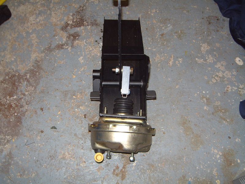
                          The Marlin pedal box does not align the brake pedal with the master cylinder (seen here with the original Metro servo)


                          It is therefore important to allow the servo input rod to align with the servo and NOT with the pedal. This either requires the holes in the clevis to be elongated slightly, or better still fit a rose joint.

                          As Mike had experienced problems we decided a rose joint would be a better engineered solution. This requires a 3/8" UNF thread, but a 10mm eye hole to fit the Marlin brake pedal bolt. Unfortunately all the female rose joints advertised are not quite long enough to be fitted straight on to the servo push rod. The simplest solution is to obtain a male threaded rose joint (3/8" UNF x 10mm eye) and a 3/8" UNF collar.


                          These can then be screwed straight on to the servo


                          An important part of the set up is to set the adjuster screw so that it is just short of touching the master cylider push rod. On all the Sierra master cylinders I have come across this appears to be flush with the mating surface of the servo (or adaptor plate if used). This should be checked either by measuring the depth of the master cylinder pushrod relative to its mating face, or by offering the servo to the master cylinder and extending the adjuster rod untilthe two surfaces touch with out starting to apply pressure to the master cylinder input shaft. This is easy to detect as the adjuster begins to be over extended the servo and master cylinder mating surfaces "rock" on the pivot of the push rod/adjuster. By backing it off at this point the optimium length can be determined accurately.


                          Note - over extending the output adjuster means the master cylinder never returns to its rest position, so can not release the brake fluid back to the reservoir; this then leads to a build up in pressure in the brake system. In both cases where brake binding had been reported the adjuster screw was set too long.

                          The likely reason for the owners over extending the adjuster screw is interesting.

                          The new Dual servo generates more boost than the Metro servo, therefore the pedal travels further for the same foot effort, and feels like the pedal travel is longer. In both cases the adjuster screw had been deliberately extended by the owners to try to compensate for the longer pedal feel - with the unfortunate and unexpected consequence that the brakes began to bind.

                          The updated Dual servo kit now looks like this:


                          Any owner with a non Ford Sierra servo will be impressed by the improvement this brings to their brakes: it finally makes our cars safe to drive in modern traffic.

                          I currently have two servo kits remaining, and do not intend to source any more as over 50 owners have now adopted this servo, and I am guessing there will not be sufficient new owners to make ordering a batch worthwhile.........so when these are gone, they are gone!

                          Regards to all who helped with this project

                          Mike

                          .............. and now I better get on with my own build again!!!
                          Last edited by Mike; 10-08-13, 07:41 PM.

                          Comment


                          • Re: Mike's Cabrio Build

                            Invisible ink Mike ??

                            Comment


                            • Re: Mike's Cabrio Build

                              What colour scheme are you using DC? - could it be the Marlin style? - I can see everything - I'm using the maroon colour scheme: I think it is much easier to read.

                              Its very easy to change: Scroll right down to the bottom of the page: bottom left corner there is an option box: select maroon & grey and everything is much easier to read.

                              Mike
                              Last edited by Mike; 10-08-13, 10:28 PM.

                              Comment


                              • Re: Mike's Cabrio Build

                                Strange thing Mike, in MikeJJs thread all text is fine and readable. Here in your build diary post (identical I presume) I cannot read anything until "A couple of days later..............was had by all" which is in normal text/colour, and thereafter all is also unreadable.

                                The pictures are all fine.

                                Wierd innit

                                Comment

                                Working...
                                X