Re: Mike's Cabrio Build
The IVA requirement to tether the cap is only if the key can be removed when the cap is unlocked. The requirement changed several times so see http://www.dft.gov.uk/vosa/repositor...n%20Manual.pdf section 3A requirement 16


-
Re: Mike's Cabrio Build
Not the cap as such but the top of the neck because it's metal and mounted in GRP and when you fill your car you should touch the filling nozzle to the neck to earth it before pulling the trigger. A few years ago Vauxhall had to recall loads of Astras as the rubber grommet was isolating the neck from the body and they had to intall a connecting cable to earth it.Last edited by b_caswell; 12-04-13, 11:32 AM.Leave a comment:
-
Re: Mike's Cabrio Build
Thanks Ben.
Although I have isolated the tank from the straps, I have made a connecting bridge in one place between the two, so that the tank is grounded (it is a requirement for IVA).
But you have reminded me that I still have to make a tether to retain the filler cap to the neck for IVA.
Are you suggesting the filler cap has to be earthed also?Leave a comment:
-
Re: Mike's Cabrio Build
Mike, you need to consider installing an earthing link between the filler cap, intermediate metal componenents and the tank and then to earth, this prevents static build up in(electrically) isolated metal parts, thus avoiding the possibility of a spark when you fill up..Originally posted by Mike View PostLast edited by b_caswell; 12-04-13, 11:31 AM.Leave a comment:
-
Re: Mike's Cabrio Build
Ok - its payback time!
Can any of you 800-ish visitors to my build help me with sealing my boot, please?
Boot lining 2.jpg
I have used a sheet of Polyurethane to line and seal my boot, and then layed a sheet of rubber lining in to finish it off. This will have sealed the floor itself.
However, the final area to make water tight is around the oblong cut out at the back in to which the lid closes. Although the lid fills much of this area, when closed, it does not come close to making a watertight seal?
Is it best to try to make a seal along the three edges to the boot lid?
Or is it better to use an impermeable membrane attached along the three edges and take it down to the say, the hinge line, on the boot lid, so that it creates a permanent physical barrier?
Photos would be appreciated if you have any good solutions.
Many thanks
MikeLast edited by Mike; 12-04-13, 10:29 AM.Leave a comment:
-
Re: Mike's Cabrio Build
Just a quick interjection really - I have a day off today, and I want make some real progress on my Cabrio today - after all its "This year" that it gets registered! I guess its become apparent in my diary I have deliberately not put dates to what I have done - I know I've modified a lot as I've gone along, but 7 years is still too long...................!
Basic Steering
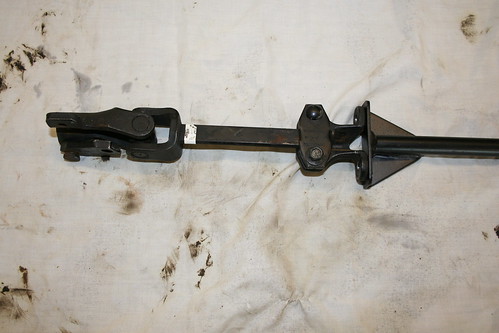
You may recall earlier on Marlin sent me a lower steering column link that did not appear to match up to anything in my Sierra steering system.
The end on the left had a long hexagonal nut, and on the right there was a flat plate at right angles to the shaft - what were these supposed to connect to?
There was no way I could work it out from the manual. Marlin did n't bat an eyelid when I explained that what I had received did not match what they show in their manual - "Oh you need a new lower U/J. Oh, yes, and we've changed the design of the fitting at the top end. Bye!" terry is no pussycat, but eventually she sent me the lower link as part of my kit that I'd paid for, and I just left it, to get on and solve the arrangement myself.
If Marlin did After Sales Service.................................it would probably be a first!
Eventually I determined Marlin intended this shaft to connect to half of the top rubber UJ in the Sierra system, and the bottom now fitted in the new UJ which connected to the steering rack.
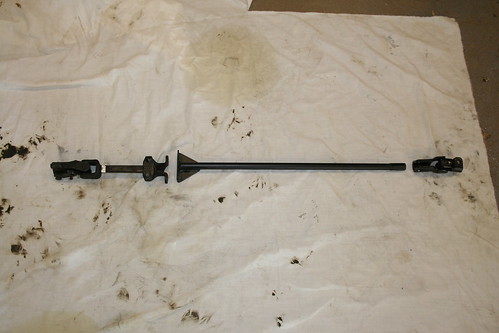
Does anyone have a Cabrio lower steering linkage layout like this?
For me it looks like a dog's breakfast of a solution - so I changed it!
I cut the long hex nut off, and threw the rest away.
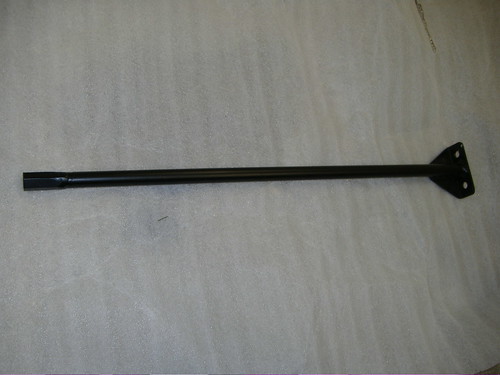
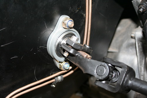
I reasoned I only needed the Sierra UJ at the top that has the triangular connection to the Sierra steering column shaft, a fixed length shaft, and the long hex nut to go into the newly supplied lower UJ. This is how it now looks:
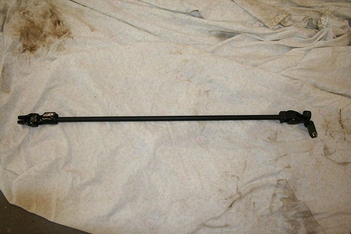
Much neater (shame I rotated the photo angle 180 degrees)
The UJ with the triangular clamp from the Sierra has been retained (on the right). I then welded a new single piece shaft to it (the UJ was immersed in a bucket of water while we welded it, to stop the heat messing the UJ up: and then the long hex nut was welded on. This retained the slide-in- pinch-tight connection to the lower UJ, which gave me the little variation in length I would need to make the final install in the chassis.
Yet another good idea I copied was the bulkhead bearing arrangement. I first saw this on one of Cameron's posts, and I know he copied it from the Locost guys.
This is a proprietary 25mm bearing with the Sierra inner bush pressed in firmly ( the one with the triangular shape inside).
So much nicer than the standard Sierra nylon bush in a nylon housing - it is much smoother, and will last a life time.
Next up, I promise will be the Body Panels, but it will have to wait - its time to go and play today!Last edited by Mike; 12-04-13, 06:58 AM.Leave a comment:
-
Re: Mike's Cabrio Build
For anyone who read my post this afternoon, I have just been back and added a couple of photos.
Perhaps this is not good practice, and I should make a new post, but I am trying to make each post a complete topic in itself, if possible.
Next time.......... Body Panels, with lots of modifications to improve upon Marlins best efforts.Leave a comment:
-
Re: Mike's Cabrio Build
Header Tank & Wash Bottle
Although a long way out of chronological order it seems appropriate to move onto my header tank, and washer bottle - you'll see why very soon.
I don't throw interesting and useful looking things away - its a trait I have inherited from my father.
Removing the central exhaust silencer left me with a long round shiny tube on a shelf - it had to be worth saving.
Around the same time I went to another Stoneleigh show, and had my usual drool over the well presented Cobras - I particularly like those from Dax and AK Cars - if I had the money, that would be my next project!
I found myself chatting with the owner of AK Cars, and we discussed how some things took a huge amount of time to make compared to their sales value, while others took little, but could be sold expensively. To make the point, he highlighted their oval stainless header tanks - even though he charged £280 per tank, and there are two in their Cobras, he reckoned he struggled to break even on them! By comparison, their stainless engine bay linings took little time to make but could be sold at a good margin.
I was taken by the oval header tanks: he explained how he made them. It all started with a round stainless tube, which if carefully squashed .................now you get where this is going?
I came home, cut the ends off my silencer, removed the internals, and I had me an 80mm diameter stainless tube. I cut a section off and tried to squash it oval: it is surprisingly difficult to do well: it behaves differently along the seam weld.
I started again with another section.

Because I'm regaling this out of chronological order, I need to provide some additional detail.
My first expansion tank was derived from a VW Golf Mk1. I bought it because Chris Cunliffe had one in his M50 Cabrio - so, I fitted one in the same position in my engine bay (don't reinvent the wheel etc......). Well this is one of the few occasions where this mantra let me down.
Unlike many builders, my engine and all its ancillaries were installed and complete for probably 2 years before I finally started the engine. The exhaust was complete, the cooling system was complete, the electric fan installed, the lot. So when I finally had the engine running I could leave it to reach operating temperature. This is when I found I had a problem. The expansion tank over flowed, dumped its coolant on the floor, and when it cooled down, did not hold sufficient to keep the radiator full. The system then sucked air back in, and the next time I ran my engine up to temperature it all began to boil.
I needed a different expansion tank arrangement.
After considerable thought I worked out I need an expansion tank of at least 800mls positioned above the top of my radiator. The Golf tank was the wrong shape, and in the wrong place to achieve this.
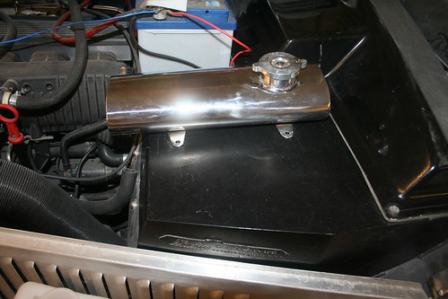
The only place I could position a tank which would be above the top of my radiator, but remain below the bonnet, was on top of the bulkhead. To contain a litre it would have to be relatively wide and flat.
An oval would be a very elegant wide yet flat solution.................
Back to its construction.
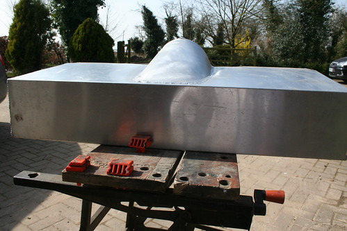
You may recall I made my radiator as physically big as was possible to fit in inside the Cabrio's nose cone - there was no room for a pressure cap. It would have to go on the expansion tank.
AK Cars were prepared to sell me one of their machined stainless necks, and gave me the dimensions.
Some more Blue Peter cardboard cut outs showed this was possible, but be a little flatter than first thought to keep it below the the tank would have to have to be flatter where it fitted to keep it below the bonnet.

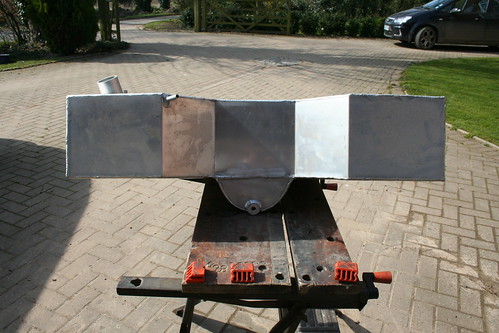
Once I was happy with the over all shape I traced round the two ends on to a piece of flat stainless, and cut two plates out. I then welded it all together and I had a posh stainless tank.

This just fits beneath the bonnet.
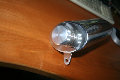
I am not into bling, but I was very impressed with the header tank, so I decided to make myself a matching washer bottle from the remaining length of exhaust tube. Same process, except this time I wanted a screw on cap.

Believe it or not, the only place I could find a small one was from Australia. It wasn't cheap at £33, but since all the rest was just my time, its made a fabulous washer bottle for a reasonable outlay:
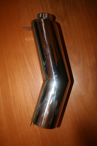
After I posted this up on the Forum, Dave Kitson kindly pointed out that IVA will require a minimum of 1 litre capacity for my bottle. When I measured it, it would only hold 900mls!
So I had to extend it!
I know it looks an odd shape, but this follows the line of the front bulkhead, and actually looks very neat in situ.
- Oh, and it holds 1.7 litres now!
 Last edited by Mike; 11-04-13, 06:41 PM.
Leave a comment:
-
Re: Mike's Cabrio Build
The Exhaust
I always knew I wanted a rear exit exhaust. I also felt that 6 cylinder engines of the 70s and 80s sound much richer than the super muffled modern version we hear (or don't hear!) these days.
I had built my original Roadster with the Triumph 2.5 straight 6 because I liked the sound of that engine in the 2.5 PI saloon, and particularly in the TR5/6s of the day. This is why I chose a straight 6 engine for my Cabrio. And since I liked the sound of the TR5/6 it seemed a good starting point to base my Cabrio exhaust on those components.
Research had also shown me that my BMW M50 engine (manufactured in July 1993) fell outside the rules for later engines to be fitted with CATs (manufactured after August 1995). So, I would not be constrained by emissions, and could try to mimic the TR6 exhaust, albeit that I would be curtailed a little by modern decibel restrictions.
I did a lot of careful measurements long before designing my exhaust, going right back to when I modified my transmission tunnel, and later when I raised my fuel tank. I was quite confident I could fit a pair of oval TR6 Sports exhaust silencers under my fuel tank, and still have sensible ground clearance. I could even squeeze a round silencer within the confines of the transmission tunnel/seat recesses below the prop shaft!
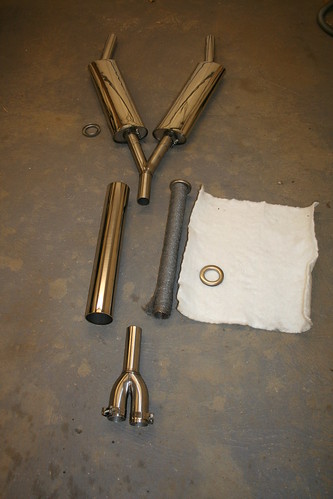
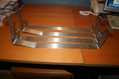
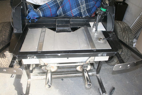
The components for my exhaust, laid out roughly as I planned to fit them - the tail pipes are not welded on at this stage.
I had no great desire for a stainless exhaust - infact I think I would still probably prefer a mild steel one for the richer sound, but when I tried to source the components, I had little or no choice. Replacement exhausts come in Stainless for the TR6.
I found the manufacturer of TR6 Sports exhausts down in Cullompton ( Devon), and he agreed to make me some extended length TR6 rear silencers (made up in stainless), together with a front Y to connect to the standard BMW twin exhaust down pipes, and a rear Y to my design to part around the diff, plus a length of tube, and the internals and end caps to make the central silencer to the final length I needed when I had fabricated the front and rear components.
The tail pipes were special.
I wanted a refined deep rumble, not a loud farting noise, that so many boy racers get from the bucket sized tail pipes they fit these days. I specified standard TR6 large bore tail pipes, but fitted with a perforated liner that stops the megaphone effect, and of course the IVA friendly rolled ends.
The tail pipes were supplied loose, and over long, so that I could cut and weld them on to the right length and angle when I knew where I wanted them to go.
There was quite a bit of trial and error. Obviously the start was determined by the BMW down pipes, but the rest had to be made up as I went backwards: and all the time I had very little space to play with as it passed along the tunnel, between the seat recesses, and then picked its way between the trailing radius arms, and diff, and finally parted around the fuel tank sump.
Until I ran my engine for the first time, (two years later) this was the design of the exhaust:
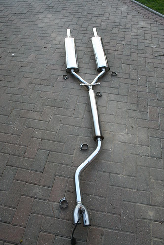
The centre silencer ran between the seat recesses, with only 10mm clearance on either side, and the middle support bracket held it rigidly in place on two short rubber bobbins.
This shows the Y section (after several modifications) passing between the trailing radius arms and the diff, and taking the two rear silencers either side the diff and petrol tank sump. It had all been planned, and eventually it did fit!
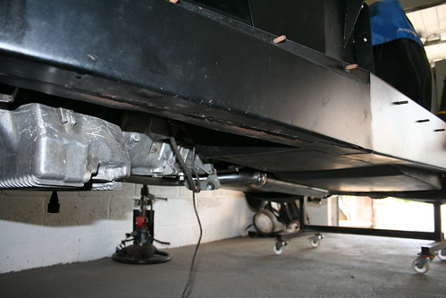
Two years later, when I finally had my engine running I found I had made it too quiet!
I had also begun to have serious doubts about mounting the exhaust so rigidly, and only having 10mm of clearance between the central silencer and the tunnel.
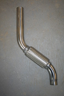
The fact that it was so quiet was a god send in hind sight. It meant I could remove the 80mm diameter centre silencer completely, and replace it with a section of ordinary 50mm tube. This in turn meant the whole system could be mounted less rigidly, so I took the opportunity to fit a flexi section at the front, which will be great for taking out the engine vibration, and then changed the rear bobbin mounts, for more conventional suspended rubber rings.
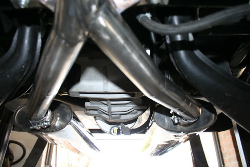
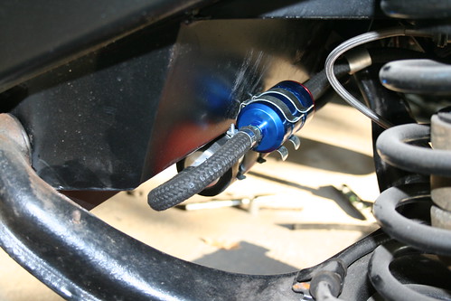
Finally to tie this section up, I fitted stainless exhaust deflectors to my new tank straps, as the IVA says leaking fuel must not be allowed to fall on to a hot exhaust,
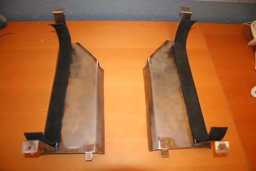
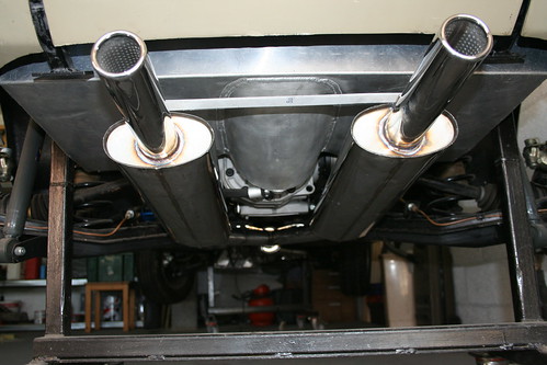
This shows the tail pipes fitted with the perforated liner which reduces resonance: the deflectors between the fuel tank and the silencers: and the less rigid rubber rings supporting the back of the silencers.
For the curious, the little black cone and pipe in the centre at the top is the standard Sierra fuel tank vapour vent pipe.

I am under the impression that I'll still have to fit some edge protection to the main oval ends of the silencers and the deflectors to get through the IVA test - wouldn't want to back in to someone , knock them down, crush them, burn them, AND cut them on a sharp edge!Last edited by Mike; 11-04-13, 01:44 PM.Leave a comment:
-
Re: Mike's Cabrio Build
The Heater
The water heater hoses on the BMW M50 are on the near side, whilst the Sierra heater has its unions designed for the Ford engine on the off side.
Another simple solution I copied!

Standard 22mm copper pipe is perfect to connect to the BMW hoses, and then reduce down to 15mm copper for the Ford
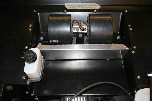
The Cabrio uses the standard Sierra heater. Marlin tell you how to mount the rear of the heater, but leave the problem of the front mounting to the builder! Only one of the tags used in the Sierra can be re-used in the Cabrio - the one on the left sits under a void in the scuttle top moulding. And even the usable one is directly beneath the battery making a simple bolt fixing undesirable.
I chose to make two new holes (visible in the foam at the front) into the lattice edge of the heater casing, and was able to nut and bolt this to the scuttle moulding quite easily.

Due to the age of the Sierra donor, all the foam had perished so I replaced it with self adhesive skinned foam.
This shows the benefit of making the battery tray flat - I have fitted the clutch reservoir in the battery space, and still have more than adequate room for the full sized BMW battery.
I've included this to show just how tight the BMW M50 engine is in the Cabrio!

There really is only 10mm between the head and the bulkhead.
Inside the cabin I intend to make more use of the Sierra heater than Marlin suggest, but I'll incorporate that in with my overall dash design.Last edited by Mike; 11-04-13, 12:12 PM.Leave a comment:
-
Re: Mike's Cabrio Build
Hugely enjoyable read Mike. Does this mean that you have finished and WHEN are we gonna get the chance to see it?Leave a comment:
-
Re: Mike's Cabrio Build
Fuel System
I bought Marlin's "Deluxe" 11 gallon aluminium tank, on the basis I needed a tank, I wanted a big one to be able to tour, and it is a bespoke item.
Several of the Sportster guys on Madabout Kitcars either had built their fuel systems, or were discussing it at around the time I wanted to install mine. There appeared to be two options:
A low pressure fuel pump from the main tank, to a small surge tank and back top the main tank, then a separate circuit with a High Pressure fuel pump from the surge tank to the fuel rail and back to the surge tank.
Or,
Add a sump to the main fuel tank which ensures a constant source of fuel, and use a High Pressure pump to feed the fuel rail and return the excess fuel back to the main fuel tank.
Sytec seem to be a big name in fuel pumps, and a very useful chat with one of their engineers suggested the latter is much simpler, more reliable, and cheaper if you can make a sump for the tank. So that's what I did.
This is Marlins's standard tank, with the half moon sump added in thick gauge aluminium. The design picks up on the fact that the tank sits behind the Sierra diff, which projects down below the level of the tank. I concluded that if I made the silhouette of the sump slightly smaller than the diff, it would be totally protected by the diff from any road debris, or humps etc.
I did not want the sump on show at the rear of the car, so I feathered it out to no depth at the back of the tank.
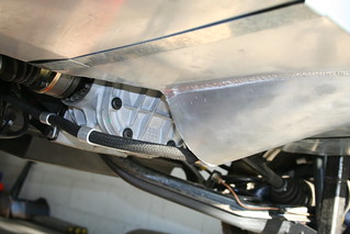
This shot shows how the sump is "hidden" behind the sierra diff.
Making the sump was more complicated than it looks, as I wanted to achieve a 2 litre capacity, to avoid any fuel starvation on a low tank of fuel while cornering hard. I rolled a sheet into a half tube, but because I was feathering it out at the back, I lost width, and therefore volume: so I had to make a compound curve, which is far easier said than done: essentially the curvature at the front is much greater than at the back.
Once I had achieved the rolled shape I was not sure how to cut the final sump out of my rolled sheet to end up with a continuous flat surface to weld to my tank. I had a half crescent tube, which I wanted to cut at an angle along it?
The solution came from immersing it in a tray of water at the angle I wanted to weld it to the tank, and by marking the water line, I had the perfect line to cut along to make a flat surface. Neat !
Before welding the sump on, I drilled a circle of holes in the base of the tank to ensure the sump would always be supplied by fuel in the tank.
The tank is held in the chassis by two flat straps. Initially I used the thin Marlin galvanised straps. Much later in the project a couple of members highlighted failures of these straps through corrosion, leading to some alarming problems, so I made myself some wider and thicker stainless steel straps. I also designed them to accept a neoprene strip lining to reduce cathodic corrosion between stainless and aluminium.

This is the tank as it is installed now:
Marlin explain the principle of venting the Sierra tank, yet the Forum suggests a few builders have struggled with it - Peter Morris turned it into this very elegant and simple arrangement - I'm all for copying good ideas!
Note the main fuel pipe from tank to Sierra filler neck has been replaced with the proper petrol grade rubber hose (the one shown would have failed IVA)
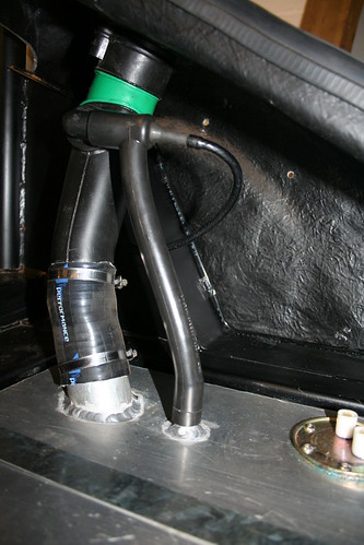
There are a couple of important points to be seen in this photo.
Marlin advise setting the tank down 25-30mm relative to the chassis rails - I chose just 5mm - to accommodate the sender flange: I bent the electrical terminal fittings over 90 degrees to reduce the clearance required for these.
This gained 25mm in ground clearance as it allowed my exhaust silencers to come up 25mm too.
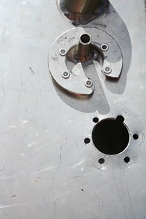
Also just visible in the shot above is the fuel sender flange. The fitting of this was made easy by copying another good idea - The Rivnut C-ring see below.
The outer small holes in the tank are drilled using the sender gasket to determine their exact positions. This is also repeated in the C ring. The Rivnuts are then set in to the C ring.
I made my C ring too wide really, it could have been thinner and would have looked better, and been easier to get inside the tank. I left it as it was because it was stronger, and will never be seen again!
Its actually much easier than you imagine to get the C ring inside the tank and maintain a grip on it, whilst at the same time entering the sender through the hole, and then fitting the first screw through the sender/gasket/tank, and then into the first Rivnut in the C-ring.
Once one is fitted the rest are very easy.
The beauty of this solution is that it is easy to make a good seal between the sender lid and the tank. I used some blue Hylomar (petrol resistant) as well as the thin gasket to improve the seal
For the main fuel lines Sytec advised fitting the High Pressure fuel pump below the level of the sump, to ensure it always has a gravity fed supply of fuel - these pumps are prone to quickly burning out the tips of the pump vanes if allowed to run dry.
Over time I have changed the bracketry for my pump, and the type of fuel pipe - bio fuel is now being used which rots ordinary fuel pipe, so I've converted my fuel lines to R9 grade pipe which copes with ethanol.
The blue cannister is the pre-pump filter. These high pressure pumps have very low tolerance to debris in the fuel so its best to run a good filter before the pump.
Several builders have also suggested the filter gets blocked quickly when you first start to use the car, as putting petrol in the aluminium tank seems to clean of any film on the aluminium tank. However, after the first quick change, it all seems to settle down OK.
The High pressure pump is attached to the under side of the original seat well - it is not exposed however, as the seat recesses provide perfect shelter.Last edited by Mike; 11-04-13, 11:22 AM.Leave a comment:
-
Re: Mike's Cabrio Build
As I am writing this build diary up, I've come to realise there is not much I haven't modified along the way - I knew there was a good reason for taking 7 years to build it!
The Battery Tray
I have another pet hate - vehicles with duff batteries. It comes from using my father's now very old tractors, and forklifts that never b****y start when I want to borrow them! Invariably I have to go and find the booster charger, and wait 10 minutes, and even then have to squirt Easystart in to the air filter. Half an hour jobs take more than that to get the b****dy things going!
So, I vowed I would fit the BIGGEST most powerful battery I could in my Cabrio. I had a chat with our local auto electric supplier, and he told me the size of the standard battery fitted to the BMW 325i. Armed with this I went and checked my battery tray - it would n't fit.
So........you've guessed: I modified it:
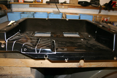
The Marlin Cabrio is a Sierra based kit; it was designed for the heater pipes running from the Ford engine through the bulkhead to the heater on the off side, and the battery tray was designed to kick up over them (the area shaded in white tipex).
The BMW engine has all its pipe work on the near side, so the Sierra holes in the bulkhead and therefore the hump in the battery tray is redundant - so I removed it.
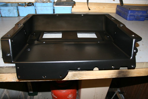
This has allowed a longer, heavier duty battery to be fitted.
The one problem I have created for myself, is that the height of the battery means I have to undo the rear bonnet hinge to generate sufficient headroom to lift the battery out! However, it has a 5 year guarantee, so that's not too big a hardship.
Whilst I am into the GRP side of the build, there is an infamous problem with the Cabrio's boot lid - THE HUMP!
Marlin state in the manual, and I quote:
"The top inside piece of the drip rail may need to be shaved away for fitting clearance. This point on the boot lid as supplied may be found to be raised slightly. This is to allow for the weight of the spare wheel"
Raised slightly?! - it must be 15mm too high!
I had stored a Sierra spare wheel on my boot lid for 2 years, and this is what it looked like afterwards! How long does it take to settle????
If you look closely at the photos above, you can just see the corners of the lid slope away significantly.
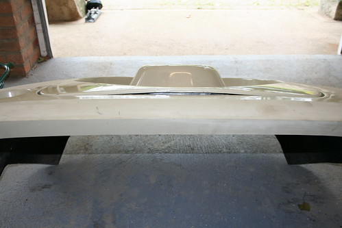
It struck me it might be possible to warm the GRP up slowly, and then clamp a straight edge across the top of the lid, let it cool slowly, and the hump might be successfully removed.
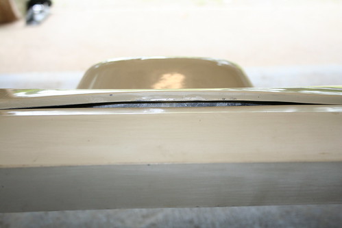
I spent two hours with an electric air gun gently warming up the lid, so that it did not damage the GRP, then clamped a straight edge to it, and this was the result:
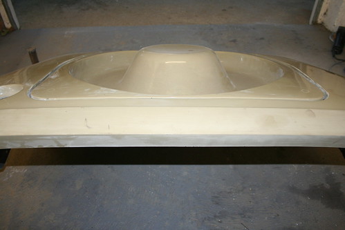
I think I can be forgiven for thinking I had been a pretty clever little boy, and resolved the problem beautifully. It looks pretty good. ( though it doesn't stand close scrutiny - the top edge works beautifully, but look 100mm+ down the sides and the old dip is still apparent).
However, it seemed to me a big improvement over the original shape.
But that's not the end of the story.................Last edited by Mike; 10-04-13, 09:50 PM.Leave a comment:
-
Re: Mike's Cabrio Build
There are some parts of my build that have given me a huge sense of satisfaction
My grille is one of them.
In 1990 I had a go at building the Marlin grille.....................
Assembling Roadster Grille.jpg
Its great how fashions come around again - those glasses and that tach! I recently bought a pair of the currently fashionable big black framed glasses, and thought of this photo then!
However I digress: that was as far as I got with the Marlin mesh. I really admire anyone with the dexterity to complete the Marlin grille, and make a good job of it - I certainly could not!
So there was no way I was even going to try to make my Cabrio's grille from the pack of wires Marlin sent me.
(By coincidence I have just been able to help an MOC member - Ian Schultz - who has taken on a Berlinetta build, and was looking for a set of Marlin wires for the nose cone, and forwarded my Cabrio wires for him to make good use of - I can't throw anything useful away!)
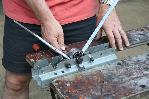
At Stoneleigh I try to go around all the Marlin models, and look for ideas. I think 2009 was the anniversary year, and there was a big turnout of all models. I came across a Roadster with a grille that really impressed me, and had a chat with its owner. Pete Beeley had hand made his own grille from stainless profile surround, and some stainless mesh. He very kindly agreed to get hold of the stainless profile off cuts from his work, and I could have a go myself.
This was the profile: its about 35mm deep. So I cut it back to 16mm deep by inserting a 5mm flat bar inside and used an angle grinder and thin slitting disc to end up with a nice straight edge. (Stainless is not easy to work with).
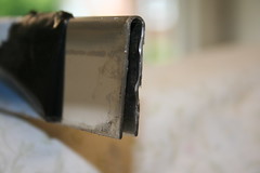
The longest piece he had was no more than 450mm, so I had to cut several sections, and would then have to weld them together to make a complete surround.
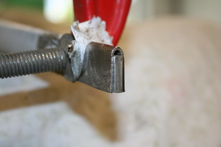
To roll a U-shaped profile to fit the Marlins nose cone was going to be a challenge. So the first thing to do was insert a 5mm flat bar inside the U to prevent it from collapsing as I tried to form it. Then I made myself a mini rolling mill from a short section of gravity roller conveyor, and a single roller that could be tightened down to the main bed to decrease the radius of the bend generated. Sounds complicated, but is quite simple:
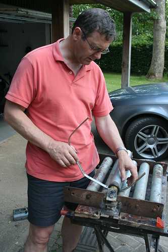
My god - these two photos juxtaposed in this thread show how I've aged in 25 years!
By rolling the profile through this rolling mill I could form a bend in the U profile, and by tightening the top roller down to the main bed I could gradually make the bend tighter and tighter.
This is the top part coming together nicely.
The lower radius in a Marlin nose cone are tighter than the top, and I found the pitch of the rollers would not permit a sufficiently tight radius. So I made rolling mill No. 2.
Very rudimentary, but very effective. 6 bearings, a section of sigma profile, and a couple of pices of angle, and a few bolts. Again, rolling the profile forward and back repeatedly, and then tightening the top set of bearings down marginally I achieved the required radius.
If anyone wants to have a go, there are only two tips. Insert a flat bar inside the U profile to stop it collapsing. The second is, as the U-profile is rolled, the inner radius material has to go somewhere, so it tries to twist. To remove the twist the material has to be removed - I used the angle grinder and slitting disc. But do it after the rolling is complete. I tried on my first attempt to slit the inner radius during the rolling process, it seemed the obvious thing to do, but it just the weakened the U-profile at the slit points, and would not then roll evenly - I ended up with a very lumpy radius, rather like a threepenny bit.
At the end of the process I had acheived this:
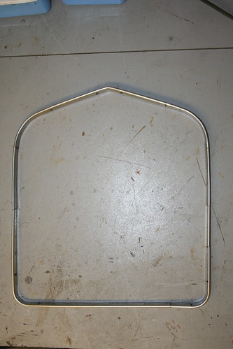
- 5 separate sections that, when welded together, would make a surround that fits perfectly inside the Cabrio's nose cone.
And laid over a sheet of stainless mesh:
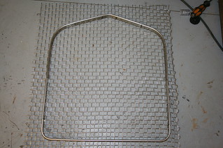
I then welded the frame, cleaned and polished it up, cut the mesh to the exact shape (using the slitting disc), and then welded the mesh to the back of the frame. Incidentally , I left the 5mm bar inside the U-profile to provide some substance to weld the mesh to:
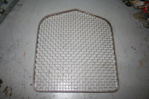
At this point I was not sure how to retain the grille in the nose cone. Some members have made it so that they can remove the grille from the front of the nose cone - I couldn't work out how to do this easily. In the end I welded some small tags on the back, glassed some nuts into the nose cone, and screw the grill into the back of the nose cone.
And the final result:
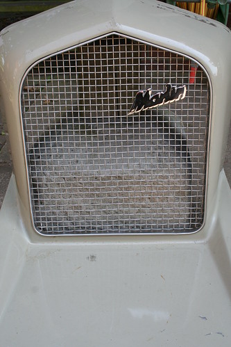
- a good copy of Pete Beeley's grille!Last edited by Mike; 10-04-13, 08:53 PM.Leave a comment:
-
Re: Mike's Cabrio Build
Once I had the engine, gearbox and drive line in position, I turned my attention to completing the physical install of the engine and all its ancillaries.
From the outset of my build there were two major concerns for me. The major surgery to the transmission tunnel was a challenge, but it was never a worry. For me it was going to be the electrics (I do not really understand it/them): particularly marrying a generic Sierra loom with a BMW engine management system. So I put that off until later - very much later!
The second was the inlet manifold.
With the engine in place, now was the time to address this issue.
As hinted at earlier, the M50 engine, with its standard Inlet manifold will not fit under the Cabrio bonnet.
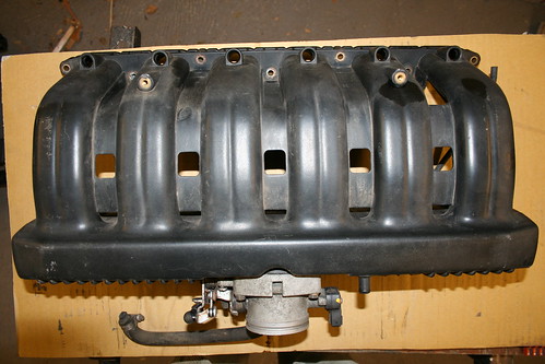
This is a standard M50 Inlet manifold and throttle body. The very sharp eyed will have spotted this is not the actual manifold I used to cut through - its a spare I bought from a scrapyard for £10 in case my open heart surgery on the original does not work!
This is the one I did cut open!
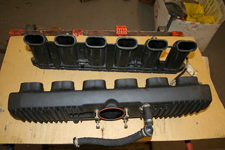
Now you get an impression of how much smaller it will be - its on the same piece of cardboard as the full manifold above.
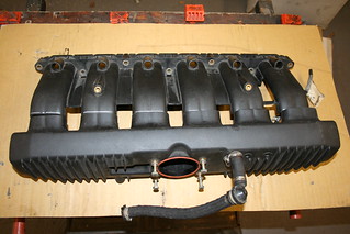
And this is what it finally looked like when I had managed to fit 6 separate sleeves simultaneously:
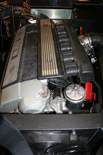
At one of the kit car shows I found a stand offering to make special laminated silicone hoses. Perversely, their normal selling point was their multi layer hoses are stronger than normal rubber hoses. However, once they had listened to what I wanted, they made me a single layered hose which was strong, but more pliable, and has worked very well.
(Its interesting to note that Marlin recommended using bicycle inner tube for the purpose!)
Note this photo shows just how tight the engine fit is: there is 10mm to the radiator, and the same at the bulkhead! It also shows how beneficial the radiator elbows were , avoiding a clash with the oil filter housing.
I was concerned that this arrangement would not be strong or robust. However, once I had cut and welded the original BMW manifold support brackets to fit their new locations, and added a third bracket connecting horizontally from the throttle body back to the engine head, it all feels unbelievably rigid.
Obviously until I've had the car on the road and achieved a few thousand miles under my belt, the final doubts will not be finally removed.
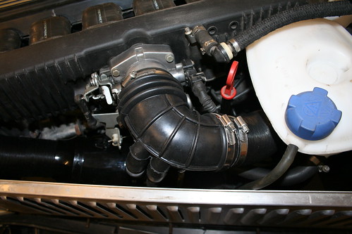
Seeing the inlet hose in this photo, prompts me to go on to show the finished design albeit out of chronological order.......some of these things take a time to work out a solution, so I go on to other mini projects, and return when I think I have a solution.
Even after removing 75mm from the manifolds width, the standard BMW 90 degree elbow does not easily fit against the bonnet side panel. Also it has two ports for rubber pipes to attach to it which are situated on the right of the elbow as you are viewing it above.
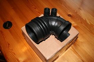
Unfortunately this elbow can not face forward as the bonnet line tapers in towards the grill.
The first option is simply to rotate the bend through 180 degrees to face backwards, but then the two ports come to the front, and face upwards! - which does not work.
Eighteen months later, I found the solution on Jeremy's own build site on flickr. He is in Ireland building a Sportster, and had the same issue. Again, the benefits of the internet, and using solutions developed by other people!
Jeremy is a doctor, and obviously a smart cookie, and used lateral thinking to solve the problem very simply: he discovered that if you fit the elbow ends the opposite way around, ie the throttle body end attaches to the filter, and the filter end to the throttle body, it can be angled backwards, AND the two ports come to the front, but this time they face downwards - so clever, and so simple!
With this conundrum solved, it was fairly straight forward to create the remainder of the induction system.
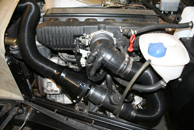
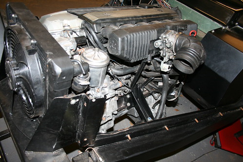
Its beginning to look like a modern engine bay under my bonnet - every inch of space is used!
I have some pet hates about kit cars and modified cars - one is air filters that hiss at you - I wanted a quiet induction system.
Hopefully, there is a theme developing here with my kit - I want a refined Grand Tourer (with some effortless poke), but do not want a high revving, noisy firecracker - I guess if did I'd have chosen a Caterham or the like?
When I did a bit of research I found some forms of modern saloon car racing have to have quiet induction systems, and they had developed a high flow enclosed air filter. Some Blue Peter styled card board cut outs convinced me I could squeeze one in, despite the lack of space, and the end result is shown above.
I have even been able to route the intake back to the nose cone above the radiator to take advantage of cold air, rather than warmed air via the radiator/engine bay.
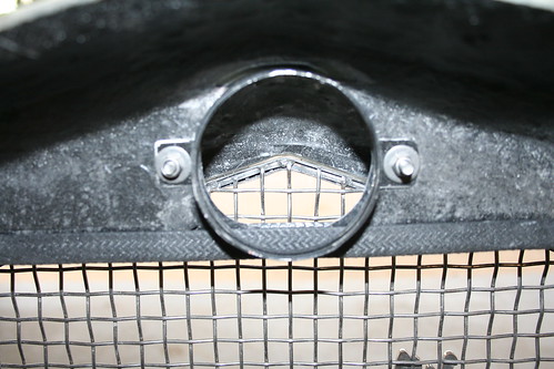
This shows the nose cone with the GRP deflector trimmed back to sit flush with the top of the radiator, and a port opened up to connect the induction pipe work.Last edited by Mike; 10-04-13, 04:02 PM.Leave a comment:

Leave a comment: