Announcement

Collapse
No announcement yet.

Mike's Cabrio Build

Collapse
X
 
  • Filter
  • Time
  • Show
Clear All
new posts

  • Mike
    replied
    Re: Mike's Cabrio Build

    I had a page like this is going to be, all typed, with photos which had taken probably an hour to prepare.........and then lost it! I know what Steve Green was complaining about now! The lack of a "save off line ", or "auto save" which it says it does, (but does not!) would have saved me from having to do this page all over again!

    It is fascinating what you can learn from the web, and just how much information is available. And if you are smart you try to find someone who has done all the work before hand! I am a great believer in not re-inventing the wheel again. I can then concentrate on things which are new or individual to what I want to achieve.

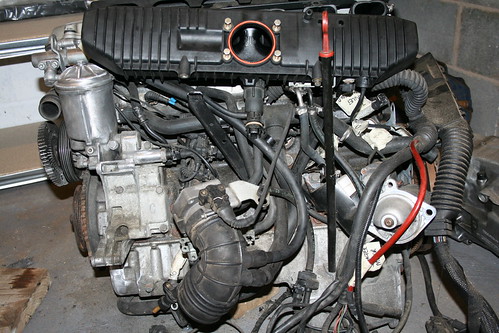
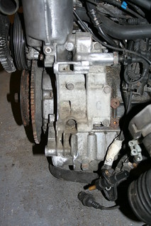
    BMW fit the same gearbox on the back of 4 cylinder engines as well as 6 cylinder ones, and also fit them in different models. So to get the gear stick in the right position for each model requires them to fit different length linkages.


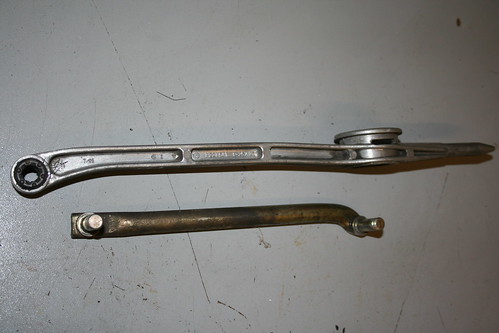
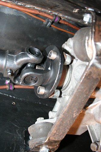
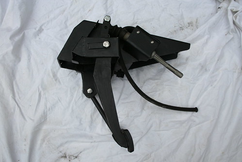
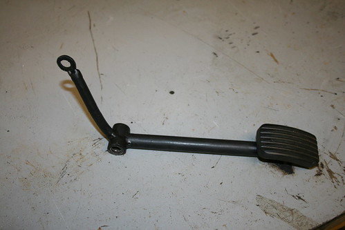
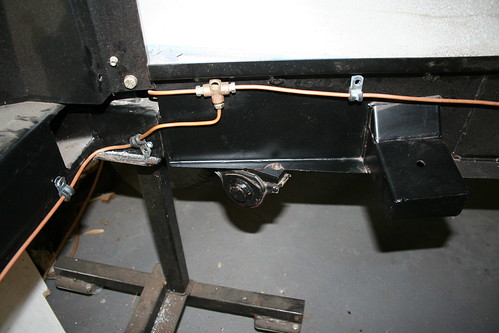
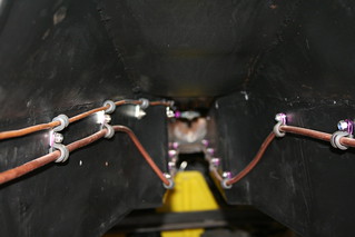
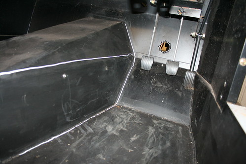
    The upper linkage connects to the back of the gearbox through the rubber mount on the left, and is supported at the rear via another rubber mount around the spiked end, which I clamped to the underside of the transmission tunnel. The gear stick pivots in a ball and cup arrangement in the circular casting.
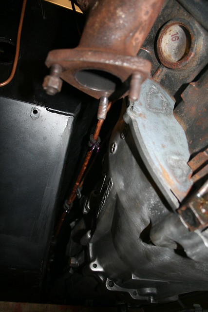
    BMW measure the distance between the centres of the gearbox mount, and the gear stick ball and cup, and then stamp it on the casting. If you blow this photo up it is possible to read "C=257.2" - very precise the Germans!

    Like a lot of kit car builders I sat in my drivers seat, made some "brrmm - brrmm" noises and considered where I would like my gear stick to be positioned in my Cabrio. After a while I concluded I'd like it 25mm further back than the link I had received with my engine/gearbox from the 325i saloon. This would "fall to hand" more easily, and provide clearance to the centre console I had in mind (much more of that later).

    A trip to Stoneleigh confirmed my thinking when I saw Chris Cunliffe had added a crank to the top of his gear stick to bring it further back into to his cabin.

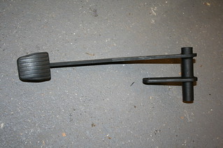
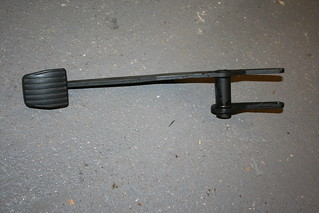
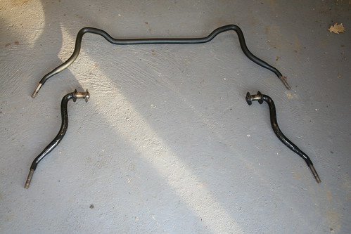
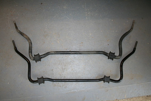
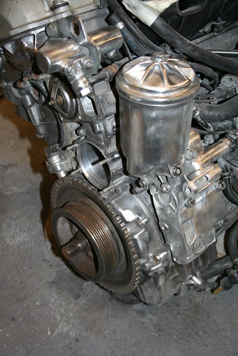
    Research then revealed that BMW made a range of these linkages, and there was one marked "C=277" which was fitted to their Compact: this would be pretty close to ideal - I could angle the gear stick back a little by shortening the lower link (as seen above) if I felt it necessary.

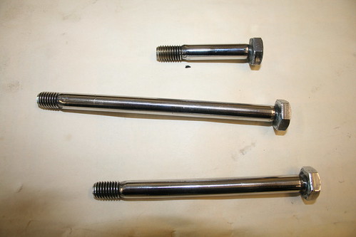
    Patrick Short had been building a BMW Sportster and had done a lot of research into BMW gearsticks, and had aquired quite a collection - see below!. They vary the length of the gear stick above the ball and cup, and the length below it; this obviously affects the amount of gear knob movement required to move between gears. I had to choose one which had a short lower length, to avoid the lower gear linkage fouling on the prop shaft.


    There are two gear sticks with short lower lengths in Patrick's selection - the Z3 1.9, and the Z4 2.5.
    The figure Patrick has typed on the centre of each stick is the ratio of upper stick length over lower length. The lower this figure, the quicker the shift is, but there is a drawback to this - the lower the ratio the harder the mechanical effort to change gear.
    So I made up some gash gear sticks and played around and determined the gear stick from Z3 1.9 would be optimum for me.

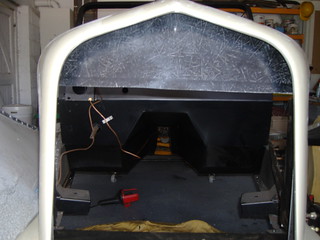
    Before showing the next photo, I should also explain that there are always competing restraints on car design. The 3 dimensional position of the gear knob is obviously determined by where you want it to drop your hand to it easily, but there are other factors to consider- in my case the hand brake position, both fore/aft, and in height.


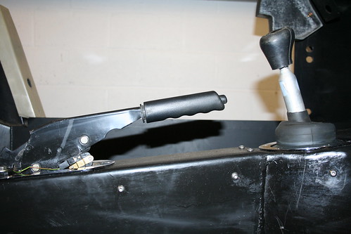
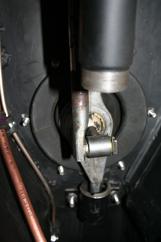
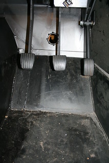
    This is with the Z3 1.9 gearstick, and a gash gear knob (a standard one with 25mm cut off the bottom to lower it to where I felt it was right). From this photo, you can see I was limited to how far back in to the cabin I could bring the gear stick by the hand brake.

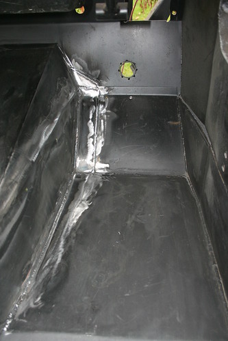
    The rubber boot came from the BMW's gaitor: it is much neater than the square Sierra gaitor, and fits nicely inside one of the chromed rings that are widely available.

    What is not obvious, is that I had reduced the height of the transmission tunnel at the back (to get access to my seat adjusters), making it slope down to the back. So, when I mounted the standard Sierra handbrake it was angled much more upwards toward the wind screen. I therefore cut the front leg off, and reduced its depth by 15mm, and at the same time welded a thicker foot to the rear fixing which, when combined, lowered the handle by around 50mm, and brought it parallel with my tunnel top.This positioned the handbrake handle as low as I could comfortably get my fingers around it without catching my knuckles on the tunnel top. It also placed it below the gearknob height - important when considering a hill start and gear change.

    Whilst at it, I welded a second foot to both the front and rear single legs, so that my hand brake is now much more rigidly mounted side to side. (Floppy hand brakes do not inspire me with confidence!)


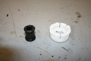
    Whilst doing all this, it also seemed sensible to fit a new cup, and rubber mount: and it did tighten up the feel of the gear change.

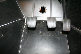
    Although a long way out of chronological order, the finished gearstick currently looks like this:


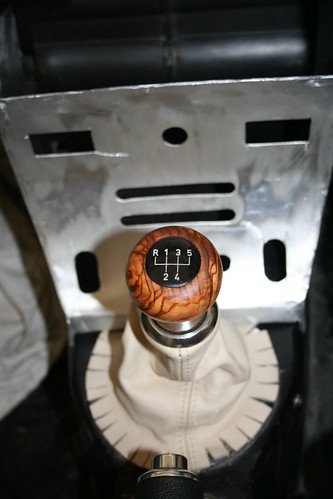
    I bought a piece of olive root in Corfu, originally crafted as a candle holder, as it had such beautiful graining: I then turned it down in to a gear knob shape. With a bit of judicious filing of the BMW gate badge and the top of the knob, it has fitted nicely.
    Last edited by Mike; 10-04-13, 01:42 PM.

    Leave a comment:


  • greyV8pete
    replied
    Re: Mike's Cabrio Build

    Hi Mike. That's very useful info about the diffs. My 3.38 one that I purchased from John at Kit Fit has the stone guard fitted behind the prop flange so I'm glad to know that I have a potentially better assembled unit 
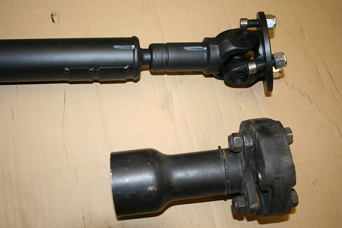
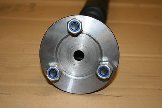
. You mention the open boss on the top for the through bolt, the 7 1/2" having a solid boss also has two shorter bolts in tapped holes in this boss, so a further identifier. Peter.

    Leave a comment:


  • Mike
    replied
    Re: Mike's Cabrio Build

    Lining up the engine took a long time, and several attempts. I think all of us who have inserted a BMW 6 cylinder have started by thinking the engine should line up "straight" in the chassis...........and all of us have eventually found it was necessary to install it at an angle to get it to clear front, back, sides, top and bottom. Even the gearbox mount is not "a given", as a small change in its height had an impact on the position of the head relative to the fire wall. I was not joking when I said earlier there is 10mm of clearance at the pinch points front, back, sides, and bonnet to ARB below!

    Sadly I don'y have any photos of the engines early days in the chassis - but fear not: there's a few showing how tight it all is later!

    So, after wrestling with the position of the engine/gearbox, I could finally take the measurements for my prop-shaft. I previously used Dave Mac from Coventry to make my Roadster prop, as he seems very good, and dispenses very good advice for free as part of his service.
    Reducing the transmission tunnel down to only 90mm internal clearance hadn't been a wild "guess and hope it would be alright". I'd spoken to Dave Mac and been told I did not require a prop the same diameter as the BMW, its diameter and step change was more to do with dialling out vibration: in fact the standard Sierra prop-shaft, although much smaller in diameter, is good for up to 350/400bhp.


    The cut section is taken from the original BMW prop, and its size relative to the Sierra prop above is clear. Dave Mac advised me not to use the rubber donut from the BMW: they are used by BMW to reduce vibration, but are very intolerant of angle changes greater than +/- 1 degree. So since my engine must be 5 degrees off straight, it was good advice.
    In order to accommodate the movement of the Sierra diff Dave recommended a splined joint.
    He was obviously very knowledgeable about both Ford and BMW prop shafts, and made up a special U/J plate to connect to the BMW gearbox spigot, and even provided turned down studs to fit the tight 3 hole fixings.

    Note: he marked the two parts of the spline to show how it should go back together as I told him I would have to split it to get it through my rear transmission bulkhead hole. ( Dave Cunnington take note!)


    This flange was turned down to fit the BMW spigot to align the flange: The turned down bolts were necessary to get them to clear the high specification U/J fitted to the prop.


    This shows the splines in spigot, giving 50mm of relative movement.

    The gearbox support can be seen here.
    This was yet another Marlin bracket I had to alter. The two rubber mounts are standard BMW gearbox mounts, and are quite large. Marlin had made the two steel angle landings too small so the rubber was locating on the angled section and partly on the the horizontal section. I may be fussy, but this is not rocket science to get right.


    This shows the turned down bolts - standard ones would not have fitted, and they are cut to the exact length to avoid fouling on the back of the gearbox.


    Although difficult to photograph, this was taken to show the prop flange has to be kept to the minimum diameter possible, to avoid fouling the gear shift mechanism directly above.

    Although this was technically quite complex, it actually fitted very easily thanks to all the additional features built in to it by Dave Mac props: I would recommend them whole heartedly.

    Ever heard of Sod's Law? If it can happen : it will !

    Since my original meeting and drive of Chris Cunliffe's M50 Cabrio we had stayed in touch, and one of the many good pieces of advice he passed to me was to change the rear diff to a 3.38 from the 3.64 - he said it transformed his Cabrio on motorways.
    I had been looking for a 3.14 diff for over two years, as I wanted a long legged tourer rather than a point and squirt Cabrio. However, in that time I only saw one for sale, and it made a whopping £350 ( for a second hand Sierra diff?!)

    No sooner had I fitted my new prop-shaft than I found a Sierra 3.38 diff in very good condition being advertised at sensible money (less than £100). I bought it, and had it checked out by Kit-Fit (John really does know his Sierra drive components), and he confirmed it was one of the very early diffs. This is good if you are in the know! Apparently Ford invested a lot of time and effort in their assembley tolerances of the early Sierra diff to ensure their longevity, and means they tend to run quieter than later ones.

    So, I had to take my old 3.64 diff out : and fit my new 3.38 diff.


    Again , I sand blasted it clean.
    If you look carefully at the prop flange, there is a steel stone guard fitted. These were only fitted to the early diffs.
    Maybe many of you will know, but I didn't, that the 7" diff can visually be identified by the open slot across the top through bolt fixing ( the 7 1/2" is enclosed), so mine is a 7".

    I have a note in my own diary that at this stage my build took 6 steps backwards!

    1 Diff removed
    2 Radiator removed - to allow engine to removed!
    2 Engine removed
    3 Prop shaft removed
    4 Fuel lines removed - due to damage when re-installing engine ( the squashed fuel line in the bulkhead)!!
    5 Handbrake removed -to allow improving clearance to propshaft, whilst lowering handle in the off position
    6 Brake master cylinder removed, and adaptor plate - I'm going to fit a Sierra master cylinder

    Just for the photo I took this shot of the drive train outside my chassis:


    And finally, while all this was removed, I took the opportunity to fit the gear selector shaft, rear support (home made half moon bracket), and make the hole for the gear stick. I thought this was going to be difficult, but I bought a nibbler attachment for my electric drill, and it made a superb job very quickly, and the end result:


    The prop shaft is shown just to highlight how close it is going to be to the gearstick bottom joint - but more of this later!
    Last edited by Mike; 09-04-13, 10:41 PM.

    Leave a comment:


  • terryreed1664
    replied
    Re: Mike's Cabrio Build

    Hi Mike, keep going, it all makes for very interesting reading. The pictures are great.

    Terry

    Leave a comment:


  • Mike
    replied
    Re: Mike's Cabrio Build

    As this is a retrospective diary I have presented some of the photos out of chronological order, as it seems to make sense to complete a topic where appropriate. I now need to back track slightly.

    When I visited FAB Recycling on the Welsh Borders, (remember I hail from the shores of The Wash, but it was via a business meeting in Cardiff, honest boss!) to view a driveable crash damaged BMW325i I liked what I saw and heard, and agreed to buy the engine and gearbox, and all the ancillaries - engine management ECU and complete loom including the connecting X20 socket, complete exhaust, including CATS, and the alternator. It only had 67,000 recorded miles, which appeared to be genuine looking at the carpets, seats, rubbers on the pedal, and the engine it self. This was very important to me as I wanted an engine and gearbox I could fit and forget.

    Unfortunately, when I received the palletised delivery a few days later, the engine and gearbox had been split - not the end of the world, but not what I had expected. But of course it encouraged me to spend money on items I had deliberately tried to avoid.
    I decided that since the clutch was exposed I would take the opportunity to replace the clutch bearing and the dual mass clutch, as these seem to have a dubious reputation in any make of modern car. It may not have been necessary, but it was so easy to do then, and so much harder if I had a problem later.

    In hindsight, and with the knowledge I have since gained on BMWs I would now change the flywheel to the bog standard M20 flywheel, which is much simpler, and therefore reliable, and is lighter. Anyway, you live and you learn......


    They were replaced and the engine and gearbox were re-united.

    As the BMW M50 engine is very tight in the engine bay Marlin supply a new bracket to relocate the alternator from the near side of the engine to the off.
    The problem I had was it assembled like this..............?


    The pulleys do not align by more than 50mm!
    Marlin don't tell you before hand,or in the manual (there is no section in the manual for the BMW engine in the Cabrio!) but the bracket they provide is for a Lucas 100 alternator (do they assume the better donor BMW alternator will be discarded?!). This was the beginning of getting to know what Marlin after sales service is like!!!!

    Rather than argue the point, it was easier, and cheaper, to cut the fixings of the mounting plate, and make them suit my BMW alternator.


    My layout has been picked up by subsequent Marlin builders using M50 or M52 engines in their Sportsters, and works well providing good lap on each pulley.
    BMW's jocky wheel has a very useful eccentric bearing, allowing very easy adjustment of the belt tension.
    Incidentally, it was very easy to obtain a 6vbelt to the length I required, from a local motor factors.

    This part of the build would not be complete without sharing a view of my my engine lifter!


    The 4m long I-beam allowed me to pick the engine and gearbox up from well inside the garage. But as anyone who has driven an agricultural forklift like this old bird will tell you, particularly with a 4m cantilever on the forks, it requires very light hands on the hydraulic controls!!!

    This was the same forklift that I used to take my chassis to the local engineering workshop to have all the transmission tunnel welding undertaken.
    Last edited by Mike; 09-04-13, 10:45 PM.

    Leave a comment:


  • Mike
    replied
    Re: Mike's Cabrio Build

    Over heating Marlin engines are a common thread on this Forum, so I decided I would try to reduce the possibility from the outset. I would fill the nose cone with the maximum surface area of radiator and fan that was possible, and seal off any air flows around the sides or over the top.

    This optimum radiator design was going to be a cross flow design, as I could position the tanks in the sides of the nose cone, and it allowed me to fit a 13" fan directly on to the core.

    When I took these dimensions to my local radiator manufacturer it turned out the depth was coincidentally the same as a Landrover's header tank, so I based the final design on them. I could just squeeze a 3 row core in, and apparently you can order cores any length you like, so he was able to make up a radiator to the exact dimensions I chose. So, I borrowed a header/bottom tank set, and took it away to mock up a "card board cut out radiator" to determine the optimum dimensions and position to maximise the radiator core in the nose cone!


    As it was going to be tight I then had special elbows brazed on to the tank to avoid wide arcing rubber elbows which would not fit.
    It all worked superbly, and made the pipework very easy. For £150, it was good value.


    The 13" Pacet fan was chosen for its 1,980 cu.ft./min flow capacity


    I supported the radiator on rubber bobbins which are attached to the front chassis cross member.

    The shot below illustrates how the radiator elbows kept the overall depth to a minimum - the two pipes connect directly to the water pump:


    Much later in the project I added a 22mm port in the side tank to accept a thermostatic fan switch:


    You may remember I had glassed in a GRP deflector into the top of the nose cone. This was trimmed back significantly to suit the height of the new radiator, and fitted with a rubber seal to ensure the maximum air flow through the radiator.

    Last edited by Mike; 08-04-13, 04:57 PM.

    Leave a comment:


  • Mike
    replied
    Re: Mike's Cabrio Build

    After I had made all of these changes and fitted, (and re-fitted!) the pedal box several times, the clutch pedal was incredibly heavy, requiring thighs like tree trunks to press the clutch down. Also there was not much travel.

    The solution was fairly easy. Marlin provide two holes in the top part of the clutch pedal. I had connected my master cylinder to the top hole - approx. 80mm from the pivot. By relocating the connection to the lower hole - - approx. 50mm from the pivot, the pedal pressure and travel was transformed to normal.

    This is a shot of the master cylinder/pedal connection before the change was made.


    Even with all of these changes there was one more piece of stiffening required!

    Once I had stiffened up the pedal box, it was alarming how the bulkhead would then allow the whole pedalbox/servo/master cylinder assembley to flex under normal braking. The whole arrangement was only sandwiched either side of the flat vertical face of the bulkhead.
    The solution is to add a reinforcing bar across the top of the horizontal section of the bulkhead that the rear part of the pedal box can be attached to.

    Finally, I had a pedal box that I could be confident would retain its strength and rigidity in the event of an emergency!

    My solution may have been over engineered, but current Sportster builders are finding the same fundamental weaknesses in the Marlin pedal box, and are having to strengthen theirs too.

    Photo courtesy of Patrick Short showing revised positioning of brake pedal - (before he found how flexible the pedal box was!)


    Patrick then chose to thicken all of the pedal box profiles by welding additional plates to "strong-back" them:


    Note the two holes below the Earth clamp: these were added to secure the rear of the pedal box to an L shaped reinforcing plate across the top of the bulkhead to stop the whole assembly flexing under hard braking.


    Patrick Short's strengthening plate Robin Martin's box section across his bulkhead
    Last edited by Mike; 08-04-13, 12:45 PM.

    Leave a comment:


  • Mike
    replied
    Re: Mike's Cabrio Build

    In retrospect it was a shame I wasn't aware there would be the opportunity to widen the footwell, as it meant cutting and welding some of the tunnel work - but that's the fun of building a kit car:


    The extra 50mm in width allowed me to move the brake pedal 40mm away from the accelerator, and the clutch 10mm away from the brake, and have more room to the transmission tunnel. It has worked out really well: the pedal centres are now identical to my A4 pedals. The before and after photos say it all.


    In order to benefit from the wider well, I had to relocate the position of the brake pedal and clutch. I already had plans to revise the Marlin pedal box, as it has a serious design fault: the clutch pedal is mounted on a cantilever bolt welded to very thin gauge steel, which allows it to flex quite badly when operated.

    Improving the design of the pedal box was really quite easy, and something I feel Marlin should have done a long time ago. By simply adding a second support to both the clutch pivot, and the accelerator, they both became much more rigid.

    Whilst improving the pedal box, I decided the crude steel tube rotating on a bolt for the accelerator, and brass bushes acting on under sized bolts for the clutch and brake could also improved.


    A 25mm piece of solid bar bored and reemed out for two small needle roller bearings provided the new pivot. I also welded on a top mounting ring to accept the standard BMW accelerator cable fixing.

    The brake and clutch pedals required more work, as they needed moving over 40mm and 50mm respectively. I made new longer central tubes fitted with needle roller bearings, relocated the original pedal stem, and added a dummy stem to connect to the servo input shaft for the brake, and the similarly for the clutch.


    To complete the pedals I also made up some special stainless steel spindles from full 10mm diameter bar, (standard bolts are often undersized, giving play in the bearing) with thread and heads welded on to give exact length required.


    The final design of the pedal box itself evolved through at least three attempts to make it more rigid - it really is a poor piece of engineering.

    The original pedal box received from Marlin:


    The brake pedal is the only one with supports at both ends. The accelerator is just about acceptable, as it does not require significant force to operate the throttle linkage, but even so it has a cantilever arrangement on the end of a long thin piece of flat steel which has no triangulation to stiffen it.

    This shows the additional pedal supports I initially added, along with the BMW clutch master cylinder:


    and with the pedals fitted:


    Even with the additional supports the accelerator pedal was not rigid, so I have since added a section triangulating the outer support back to the main box.
    Last edited by Mike; 08-04-13, 10:32 AM.

    Leave a comment:


  • Mike
    replied
    Re: Mike's Cabrio Build

    Marlin recommend fitting the brake lines and fuel pipes before installing the engine/gearbox:


    This is the engine bay with the front brakes piped up to suit the Metro master cylinder, which only had two out lets, so it was split front and back: this all changed later in the project.

    This shot also shows the split ARB arrangement - where's the centre section?!

    Even with these I had to grind the top part of the large penny washers down as they fouled the chassis. I was not happy with this at all.

    Because I have narrowed the transmission tunnel down to only 90mm internally, I had to be careful about the location of the fuel and brake lines.


    Not much room for a prop-shaft and an exhaust!

    The shot below shows just how tight the engine is in the Cabrio bay - there is not enough clearance to get an 8mm copper fuel pipe between the bulkhead and bell housing - so I had to re-direct the fuel supply through a different space:


    I offered the engine and gearbox up for trial fitting, and found the main fuel supply pipe was fouled by the bell housing on the nearside, but this minor problem was hugely offset by what I found on the Off side (Drivers Side).


    There was 50-75mm of clearance between the footwell and the bell housing/gearbox on the drivers side.
    This space was far too gret to waste, and I could not resist the opportunity to increase the width of the foot well by 50mm. It does not sound much, but 50mm extra width will make a huge difference in a Cabrio foot well. So the engine had to come out again!


    The standard Cabrio footwell is very restricted in width: I have wide size 10 shoes and was awre it would not be easy to drive, so the option to make the drivers side foot well 50mm wider was a huge bonus.
    The standard Marlin pedal arrangement and well looked like this:


    The white lines are where I intend to cut the transmission tunnel and move it across 50mm
    Last edited by Mike; 07-04-13, 04:24 PM.

    Leave a comment:


  • Mike
    replied
    Re: Mike's Cabrio Build

    Originally posted by lizbillings View Post
    Keep going - its very interesting. Only worried that it will delay you getting it ready for IVA! regards Liz

    Hey Liz - have you been talking to my wife?
    She's just given me a right ear wigging about spending too much time on the computer, and not getting on with my Cabrio!

    Must go - don't want to get caught in here today!

    Mike

    Leave a comment:


  • Mike
    replied
    Re: Mike's Cabrio Build

    5.30am is not my usual get up time! However, since I can't get back to sleep, I thought I'd add a bit more!

    Anti Roll Bar
    You may have gathered, I like to research and plan what I want to do with my Cabrio.
    Fitting a big 6 cylinder engine with a 30 degree cant into a 30's style bonnet, was always going to be tight - quite literally there is no more than 10mm front, back, sides, and top and bottom!

    At this point I need to take you back to when I placed my order with Marlin.

    Back in 2005/6 there was talk of Marlin selling the Cabrio project, and of a new, mysterious buyer, who was considering making the Cabrio a BMW 3 series donor kit.

    This had a lot of attraction for me, not because it would be a single donor, but because I assumed the Cabrio would be given the Sportster's BMW front suspension set up, which is much neater than the Cabrio's design.

    When I asked Terry if the Cabrio was a fully sorted kit, I received a very curt reply "Of course it is" - as if to say, how could I possibly think it wasn't?! Put me in my place - after all I'm only the customer!

    However, when I probed a little further about the new BMW based Cabrio, there was a much less assured "waffle waffle .....new potential owner....might go down the BMW donor route......all hush hush.....No, don't know when it will go ahead.......waffle, waffle....!"

    I had heard enough. I was not going to be their guinea pig for them to develop (and no doubt find the problems with) the new set up, so decided to take the safe "fully sorted" Sierra set up, so strongly advocated by Terry.


    ...............There are no "safe" options with Marlin!

    My digression will become clearer: back to my build.

    Chris Cunliffe had pointed out the modification Marlin had carried out on his Sierra ARB. They had removed 50mm from the forward length, and sleeved it back together. This allowed the chassis mounting plates and the central crank section to be moved forward 50mm to make room for the BMW's sump.

    So, when Marlin asked me to send them my ARB for modification, I expected the same.

    This is what I received back!


    The top one is obviously a standard Sierra ARB.

    The lower one was Marlin's modified version - how the hell does that work........?! An Anti Roll bar with no centre section!

    Safe option??!!

    Mark dismissed my protestation with a monosyllabic "It doesn't need it"!

    I was not a happy bunny!

    Whether or not the Cabrio required an anti roll bar, I was not happy with the location of my front suspension geometry being determined by two big penny washers either side of the standard Sierra's D mount to the chassis. it would allow far too much movement for precise steering.

    The one piece of good fortune about Marlin's unilateral decision to change my suspension arrangement was that they had left the chassis mounting plates in the 'normal' Sierra position.
    I was really annoyed by this, and decided to fit the standard Sierra ARB, but knowing that under full compression the centre crank was going to foul the sump. It annoyed me, but I had no alternative solution at this stage, and decided to leave this as an open issue, to which I could return later.

    Stoneleigh 2010 (ie 2 years later!) provided me with the solution! - Ford made more than one style of ARB to fit the Sierra!

    If anyone saw a middle aged man flat on his belly with two feet sticking out from under their Cabrio at Stoneleigh 2010, it was probably me! - investigating Cabrio ARBs!!!

    I discovered there are at least 3 different thicknesses of Sierra ARB, and they were all on show on the MOC stand!

    However, it was Dave Kitsons V8 Rover Cabrio which provided me with my solution. The central crank on Dave's ARB was different to all the others I had seen: it had a different crank arrangement in the centre. This meant that as his suspension was compressed the centre section moved away from his sump, as opposed to all the others which rotated towards it, and in my case fouling it.

    So, why was Dave's different? Had he had it specially made? No, it was just a standard Sierra ARB as far as he knew. This was good news.

    A trip to my local Sierra breaker - he has over 40 Sierra's and nothing else, in his yard - revealed the Sierra P100 pick up truck had the ARB I wanted.


    The two ARB crank centres are visibly different.
    The upper is the most common - facing forward and down - this one was 26mm diameter.

    The lower, is from the P100. The central crank is facing back and up. As the suspension is compressed the centre section therefore rotates down, and away from the sump.
    Problem solved.

    By chance this one is only 24mm, which I hope will be more suited to the lighter Cabrio chassis.

    Patience, and tenacity are essential, and usually rewarded, if you keep going!
    Last edited by Mike; 07-04-13, 12:38 PM.

    Leave a comment:


  • lizbillings
    replied
    Re: Mike's Cabrio Build

    Keep going - its very interesting. Only worried that it will delay you getting it ready for IVA! regards Liz

    Leave a comment:


  • listerjp2
    replied
    Re: Mike's Cabrio Build

    Keep going I will let you know if I get fed up, hasten to add I'm not yet.

    Adrian
    Last edited by listerjp2; 05-04-13, 02:56 PM.

    Leave a comment:


  • Mike
    replied
    Re: Mike's Cabrio Build

    Now we get to the exciting bit - for me anyway!

    The engine:

    I took a long time researching BMW engines.
    I wanted to go as modern as possible, to get the best fuel efficiency, but my research found that there were insurmountable security system problems (EWS) built into the electronics of anything after the M52B25. There were also issues with early M52s having Nikasil bores which were susceptible to wear from high sulphur petrol in the UK.
    So after 4 BMW breakers all told me the same story, I concluded the M50TUB25 (with Vanos - variable valve timing on the Inlet cam) had a good fuel injection system, was ultra reliable, and did not have the EWS problems to deal with.

    Marlin had built a Cabrio demonstrator with the M50 engine , and one member, Chris Cunliffe, in Devon, was building a Cabrio with this engine.
    I tracked down the owner of the original demonstrator, and invited myself over to have a look at the installation - it sounded gorgeous. I also contacted Chris at what turned out to be a very good time, just before his SVA test. He had been able to fit the engine, and without too much difficulty*. Once he had passed the test, we both drove for three hours to meet up in Cirencester, (me from Lincolnshire, Chris from Devon!) for me to have a test drive of his new pride and joy - (Kit car enthusiasts are nuts at times!) I could not stop grinning as I drove it - it was beautiful, and just what I wanted to build.

    So that was my decision made M50TUB25 - 192BHP, 6 cylinder silky smooth engine, 5 gears, and I could expect reasonable fuel economy on long runs.

    There was however, a piece of major surgery required to make the M50 fit a Cabrio engine bay - can you see it?


    BMW M50TUB25

    I spent a long time searching for a low milage crash damaged BMW, to find an engine I did not need to strip down. I visited several breaker's yards until I came across this. It had only covered 67,000 miles, with one careful lady owner (until she hit a bollard, and broke the front timing pulley, so the car was written off). Shame, really as it could easily have been put back on the road. I heard it running in the dismantlers yard, and it was quiet - M50 engines can have a "Vanos rattle" if they are not looked after, or are high milage and I had heard a few on my travels, but this one was very quiet.

    I deliberately left all the wiring and pipes in situ to know where they go later.
    Note original lower alternator support casting - it gets removed later.


    Old Alternator Mount -above
    and removed - below


    I am not a fan of engines with too much paint on them, so I cleaned and polished the alloy bits - with a stainless steel wire wheel on a drill (do not use mild steel as it reacts with the alloy)

    As BMW heads are alloy, they will not tolerate being cooked, and the M50 has a plastic water pump which is prone to failure after a while, so I took the opportunity to fit a steel impeller pump and new thermostat and housing.
    The engine is a very tight fit in the Cabrio bay, and has to be off set to the near side to allow the cant of the engine to fit on the off side. The alternator has to be relocated from the near side, to the offside, and the original lower mount can be ground off to help with the space constraint - but this is the easy bit!

    * And the dramatic bit?

    - the inlet manifold has to be cut across all 6 runners, and 75mm removed, before re-sleeving it back together - This build is not for the faint hearted!!


    Is there anyone still interested in my build?


    Last edited by Mike; 05-04-13, 03:10 PM.

    Leave a comment:


  • Mike
    replied
    Re: Mike's Cabrio Build

    Once I had satisfied myself the seats would fit, I turned my attention to the body work.
    Over 20 years ago I bought a pair of Volvo P180 rear light clusters (The Saint's car - remember him? Simon Templar/Roger Moore?). The Marlin pods are not wide enough to accept them, so I cut the pods out whole, then cut them in two, added 40mm, and glassed them back in again.


    I have always preferred proper side lights over the Marlin front molding, so I cut them out, and glassed the hole over:


    Whilst in GRP mode I added a GRP blanking plate to the nose which I can trim back to fit the top of my radiator later. A lot of Marlin owners complain about over heating, so being a great one to learn from others, I am making sure air is forced through the radiator, and not allowed to escape over the top of it:

    Last edited by Mike; 05-04-13, 03:52 PM.

    Leave a comment:

Working...
X