


-
Hmmm, issue always is that in drilling the chassis to fit rivnuts for your spare wheel bracket you are also introducing potential weakness. If it wasn't on the side of the main chassis spar, it wouldn't necessarily be an issue; but it is. -
I am a bit paranoid about carrying a spare, not convinced that the squirty tyre repair stuff works! And if if you have a puncture it's always at the most inconvenient time and place, raining, middle of the night and miles from home....
My theory with the rivnuts is that even if they allow water penetration and long term rusting of the chassis it will still well outlive me lol.Leave a comment:
-
If you're going cycle wings and don't want to have the spare on the rear tub I wouldn't bother with it at all, I think it would look much better without a spare on the side, but I know that's subjective...
The radiator mount looks nice and neat. Rather than drilling into the chassis I welded tabs on that I could bolt the radiator mount to, just a thought
Leave a comment:
-
As a prelude to making the bonnet side panels I have been playing with ideas to mount the spare wheel. The intention is to side mount it on the passenger side as the car will mainly be driven with just the driver and this will help to balance out the weight a bit. I purchased a rather agricutural looking trailer spare wheel mount from Amazon to use as a starting point. It now looks like this.
 spare_wheel_1 by Robin Martin, on Flickr
And (temporarily) mounted on the chassis rail.
 spare_wheel_2 by Robin Martin, on Flickr
 spare_wheel_3 by Robin Martin, on Flickr
I have yet to decide on the final position as the exhaust will also exit on this side. But clamping it to the chassis showed is was good and sturdy - if still a bit agricultural lol.
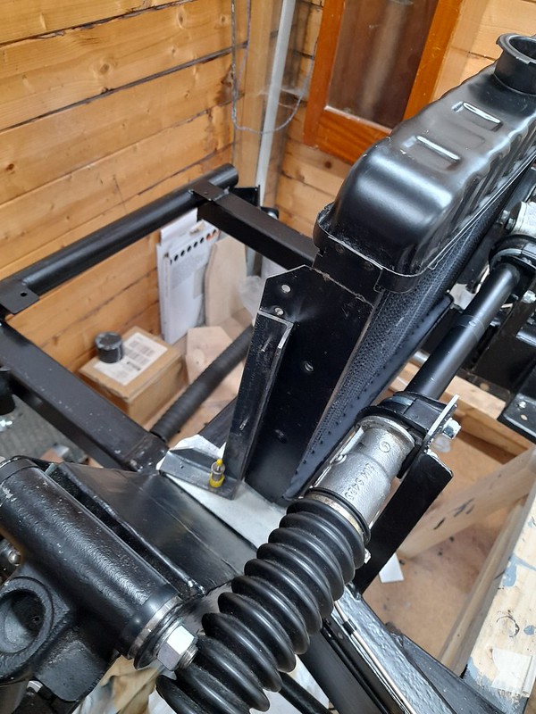
I have also test mounted the radiator. I acquired a new old stock rad from another Marlin owner. It's from a Vauxhall Chevette (Viva?) I understand. Originally the car had a heavier duty looking rad from a Morris 1800. On comparison it has more fins but doesn't have any more waterways than the Vauxhall rad so I hope the Vauxhall rad is going to be OK. It will be getting as big an electric fan as I can fit in. The original design hangs the rad on some brackets from the join between the bonnet sides and cowl. Or in the case of this car just wedged between the chassis rails.... This means that taking the bonnet sides off for any reason in the future will be a real pain. so I have made a couple of L brackets to mount it directly to tha chassis. Seems to be a better solution although it does mean drilling the chassis for some rivet nuts.
 radiator_new_old by Robin Martin, on Flickr
 radiator_1 by Robin Martin, on Flickr
 radiator_2 by Robin Martin, on Flickr
That's all for now. Bonnet sides next!

Leave a comment:
-
I have been working on the heater install the last few weeks. I bought a (fairly expensive) heater from T7Design as the basis. I don't think it represented good value for money! When i took it to bits to modify slightly I found it just comprised a computer style fan, albeit a powerful one, and a heater matrix in a simple aly box. It would have been considerably cheaper to make it myself. Ho hum - you live and learn.
The heater has 4 outlets, I used 2 for the demister vents and the others for the footwells. I added a 5th, with a little flappy outlet thingy, that points directly into the interior. The heater is supposed to be 3.5kw (hmmm) so I hope it will keep things toasty.
I replaced the heater front panel with one of my one which also serves to mount it and carries the on off switch, the above mentioned 5th vent and will also act as a mount for a 12 volt socket and the choke cable.
At the moment the heater is just configured for re-circulation, but I have allowed enough space behind it to allow for some ducting to the outside world should it prove necessary. For the moment I considered this a complication too far.
I recently discovered the Car Builder Solutions catalog and this has provided the heater hoses with right angle bends. Very handy.
 heater1 by Robin Martin, on Flickr
 heater2 by Robin Martin, on Flickr
 heater3 by Robin Martin, on Flickr
Leave a comment:
-
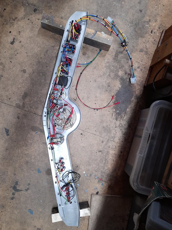
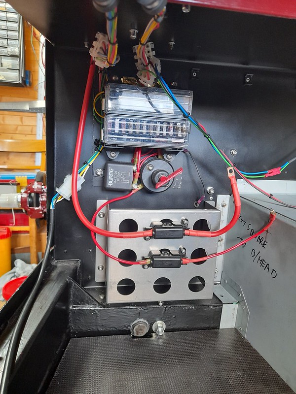
I have just about completed the wiring loom now. All I need is the engine and a few lights to connect up!
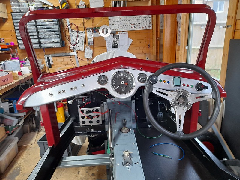
I have confined a lot of the spaggetti to the dashboard.
 dashboard5 by Robin Martin, on Flickr
The little button (temporarily) mounted on the steering wheel is actually a wireless horn button. The receiver is amongst the stuff on the rear of the dashboard. The plan is to bodge it around so that it sits behind the steering wheel central horn push.
 dashboard4 by Robin Martin, on Flickr
And a few more pictures of the rest of the wiring waiting to be connected up. All i need is the engine now!
 loom2 by Robin Martin, on Flickr
I have managed to keep the high current (starter motor) wiring nice and short. (Red)
Not sure what route I am going to use yet to reach the rear of the car but it is all contained within one cable. (Black)
 loom3 by Robin Martin, on Flickr
Leave a comment:
-
With regards to the reversing light, I wired mine up and have found it extremely useful for when I reverse into my unlit garage, after a drive. Obviously our requirements /circumstances may be different, but at least something to consider
Last edited by Ye Ol Ripper; 15-03-24, 05:23 PM.Leave a comment:
-
All comments greatfully recieved
Ignition switch is quite short. ATM it looks like there is clearance! Handbrake cable is nowhere near...
I am not bothering with a reversing light. I checked and it's not a legal requirement it seems.
Cheers RobinLeave a comment:
-
Hi Robin
1) Will you have enough clearance for the wiring for the ignition switch, push start button and handbrake cable in that location , as surely the prop shaft is running very close to them?
2) I note that the reverse light switch has yet to be installed in the gearbox , have you also sufficient clearance there to fit in situ?
3) In the early 80's I helped build a Westfield SE with a Lotus Twincam. We also used an indicator switch like that. They were used on the early London Black Taxis and also milkfloats and were on a timed release.
It is a good move as the Marina /Mini stalks don't always self cancel and in bright sunlight it is difficult to see the "tell tale" green dash light flashing.
At least you have avoided that issue.Last edited by Ye Ol Ripper; 13-03-24, 05:37 PM.Leave a comment:
-
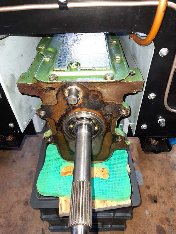
I thought it was about time to do a reality check and make sure the gearbox actually fitted in my new transmission tunnel. I had to take the hacksaw to one of the unused lugs on the gearbox casing but now it fits with about 1/2" clearance on either side which hope is enough for any movement. And the propshaft fits as well, always a bonus....
 gearbox_fit1 by Robin Martin, on Flickr
 propshaft_check1 by Robin Martin, on Flickr
From the front it looks like I may have to adjust the position of the fuel line but I'll wait untill the gearbox is finally fitted before I do that.
 gearbox_fit2 by Robin Martin, on Flickr
And I have taken the advice of various sages and fixed the tunnel top using M5 screws and rivet nuts. I have put the ignition switch on the top of the tunnel, the idea being all of the wiring is then almost impossible to get at for any would be joy rider. The switch itself is an industrial tamper proof item. NOS from ebay for a bargain tenner.
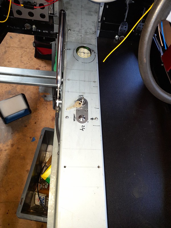 transmission_tunnel by Robin Martin, on Flickr
And yes the gearbox is almost new! It looks like it had been recently fitted before I bought the car from the previous owner and builder.Leave a comment:
-
Makes sense now.... Can't beat a good 2CV, have owned a couple over the years. Cornering is a riot and a case of trusting the car to not do a Reliant Regal on you!Leave a comment:
-
I probably didn't explain it well!
There wasn't really an oil seal in the conventional sense. The splined joint is greased. The original arrangement was just a primitive cork washer the job of which was to keep the grit out and the grease in. I think the gaiter should do the same job. It works well on millions of 2CV's!Leave a comment:
-
Very useful that these fit but surely this doesn't resolve your issue of holding the oil seal in place? Regardless of putting on a gaiter I would expect you would still need a correctly fitting oil seal.Leave a comment:
-
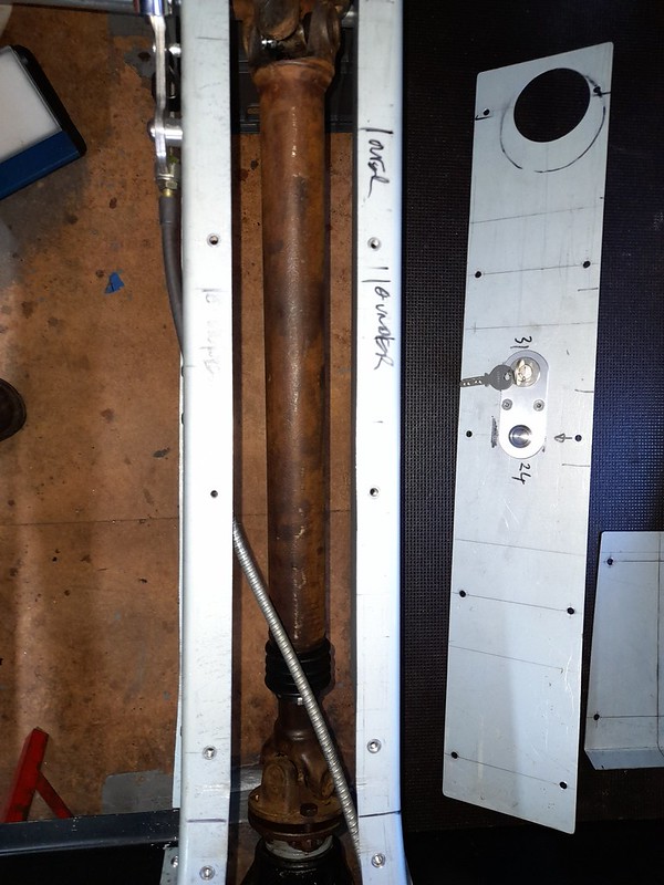
I have been pondering the problem of my propshaft for some time now. For some reason the little screwed cap that holds the oil seal on the splined joint is way to big and hence impossible to screw up. I can only think that it has come loose at some point and years of rattling arround on the propshaft joint has stretched it. Its at least 3mm too big in diameter.
 propshaft_problem by Robin Martin, on Flickr
Anyway I was doing some routine maintenance on the Pembleton. The driveshafts (2cv) have 3 joints the centre one of which is a sliding spline like on a propshaft. They are all protected by rubber gaitors. So I got out the callipers and, would you believe it, the size of the shafts making up the splined joint is almost the same as that on the Marlin propshaft. Getting excited now... So I ordered a gaitor from ECAS, the main source for 2CV spares and it fits perfectly!
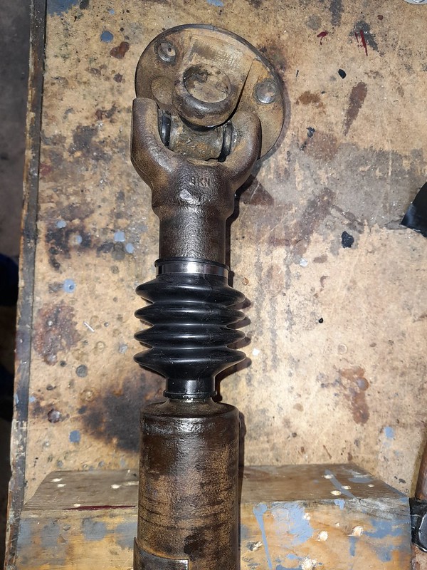 propshaft_solution by Robin Martin, on Flickr
Not very often you get a piece of luck like that.
Leave a comment:


Leave a comment: