Originally posted by martinclan56
View Post
Adrian
If this is your first visit, be sure to look in the introductory information by clicking on this link: FAQ . You may have to join as a member before you can post. To start viewing messages, select the forum that you want to visit from the selection below.
If you have questions please use the Contact Page for a personal response
If you wish to contribute to our discussions then please consider joining the club - it costs only £24 per year and is worth every penny!


 transmission tunnel 2 by Robin Martin, on Flickr
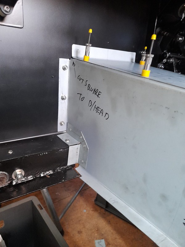 transmission tunnel 3 by Robin Martin, on Flickr
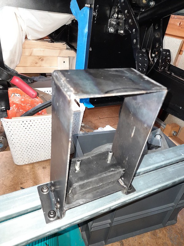 gearbox_mount by Robin Martin, on Flickr
 fuse_box1 by Robin Martin, on Flickr
 fuse_box2 by Robin Martin, on Flickr
 dashboard1 by Robin Martin, on Flickr
 dash mockup by Robin Martin, on Flickr
 wiper motor installed by Robin Martin, on Flickr
 front brake pipes by Robin Martin, on Flickr
 front brake pipe bracket by Robin Martin, on Flickr
 front suspension complete by Robin Martin, on Flickr
 pedalbox complete by Robin Martin, on Flickr
 painted scuttle top by Robin Martin, on Flickr
 coach_painted1 by Robin Martin, on Flickr
 castor_angle by Robin Martin, on Flickr


Leave a comment: