


-
Also, you may want to make an access hole for checking, topping up the gearbox oil. -
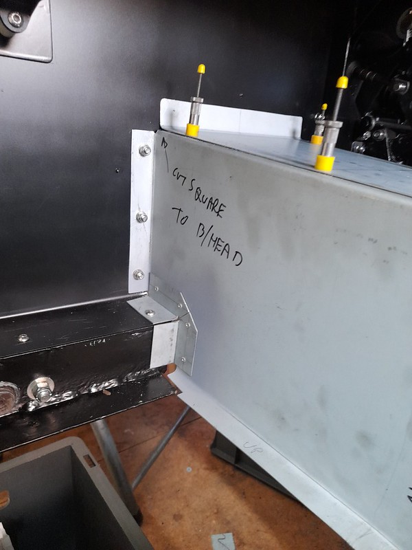
I have completed the transmission tunnel. Pleased with the result but folding the long lengths of sheet steel almost destroyed my home made bender. Steel is so much tougher than ally. Hopefully I wont need to do it again.
Getting a good fit at the bulkhead end proved tricky as the tunnel is not square to the bulkhead and the chassis that supports the torsion bars is also at a slight angle. But got there is the end after a lot of bad words....
The observant may notice that I used a stretcher / shrinker to acheive the flare in the tunnel at the diff end, and again at the gearbox end. You can still see the grip marks on the flange.
 transmission tunnel 2 by Robin Martin, on Flickr
 transmission tunnel 3 by Robin Martin, on Flickr
Next job - handbrake. I have purchased one of Richard Oakes trigger handbrakes and a lovely piece of kit it is too...Leave a comment:
-
I managed to find a few odd half hours in between being Florence Nightingale and Jamie Oliver :-)
I have completed the new gearbox mount which will also support the transmission tunnel and hence floor. It also means I can make the transmission tunnel sides in two parts that will fit in my bender.
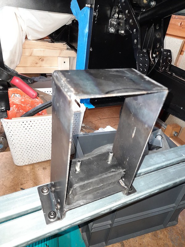 gearbox_mount by Robin Martin, on Flickr
And I also made up and mounted the fuse/relay box which will also act as a distribution point for the electrics hopefully avoiding the spaghetti look. I used a similar arrangement in the Pembleton.
 fuse_box1 by Robin Martin, on Flickr
And on the engine side two mate'n'lock connectors to avoid cables having to go through the bulkhead.
 fuse_box2 by Robin Martin, on Flickr
The battery box may or may not be fitted below the fusebox. Undecided atm.Leave a comment:
-
Yes. I have a plan for that as well....Originally posted by jon_wilkinson View PostLeave a comment:
-
It's even worse when you realise the inner seat belt mounting point was the thin aluminium tunnel reinforced only by some fabricated steel corners!Originally posted by martinclan56 View Post
Leave a comment:
-
A litle bit of progress, probably the last for a while as my wife has just this week had a hip replacement and apparently being nurse and chief cook and bottlewasher is now more important lol.
I made a backing plate for the dashboard to take the three instruments I am using. The centre place is a giant rev counter from a Jag. Left and right of it will be a fuel gauge and combined oil pressire / water temperature gauge. The plan is to make the actual dash from aluminium recycled from the old bonnet sides which I will be remaking.
 dashboard1 by Robin Martin, on Flickr
In the lower part of the picture you can see the start of my new gearbox support. Originally the gearbox was suspended from the transmission tunnel - an arrangement I didn't particulary like.
That's all for now...Leave a comment:
-
Of course, Jags have 6 cylinders and you have 4. But it's worth the effort for the look.Leave a comment:
-
Jag rev counter is electronic. But I also bought a conversion kit for it from a company called Spyder. So I have old school looks with modern electronics. Hopefully :-)Leave a comment:
-
That is looking superb I love the snape of the dash. How does the Jag tacho work? Mechanical or electric or mechanical?Leave a comment:
-
I have mocked up the dashboard. I am going for the minamilist look - large Jaguar rev-counter in the centre, standard Smiths fuel and combined oil pressure / temperature for the smaller gauges. Bicycle speedo and oddometer discreetly mounted. No glovebox as the suggested one is uselessly small.
 dash mockup by Robin Martin, on Flickr
Lucas windcreen wiper motor and boxes trial fitted. These are a real b*gger to get right but essential to do so as they are fitted in the clamp which holds the screen in place. As this is sealed in with mastic once the screen is fitted so you don't want to be taking it out very often!
 wiper motor installed by Robin Martin, on Flickr
Front brake pipes all run. I didn't follow the suggested route from the manual. I know that one of them bridges the point where the side mounted exhaust exits the bonnet side panel - but I am not going to be doing that with the exhaust anyway. I had to make the brackets for the front flexi pipes as my (very early) chassis was missing them. The flexis are a bit tight but I think they will be OK once the suspension is at its working height.
 front brake pipes by Robin Martin, on Flickr
 front brake pipe bracket by Robin Martin, on Flickr
Leave a comment:
-
A few more pictures. Having a bit of a push at the moment.
 front suspension complete by Robin Martin, on Flickr
 pedalbox complete by Robin Martin, on Flickr
 painted scuttle top by Robin Martin, on Flickr
Leave a comment:
-
The half moon shape in your front scuttle, does anything live there?
AdrianLeave a comment:
-
My first attempt at coachpainting some of the fibreglass. it's not bad even if I do say so myself. This was coat number 5 - the first topcoat. 6th coat (2nd topcoat) looked better but forgot to take a picture. Still a long way from perfect but good enough. The red, by the way, is considerably darker in real life.
 coach_painted1 by Robin Martin, on Flickr
And now I have started to re-assemble the car in ernest. Near side front suspension is done. The big problem with the Marina is you cannot adjust the castor. Which in turn affects the steering self centering - big time. But at least with my adjustable tie bars you can tweak it. By measuring the angle of the torsion bar relative to the chassis I have established that the castor is bang on the suggested 2.5 degrees. Hooray. Note the Heath Robinson angle device!
 castor_angle by Robin Martin, on Flickr
Leave a comment:


Leave a comment: